
Sealign Structure for Fitting Portion

a sealing structure and fitting technology, applied in the direction of mechanical equipment, engine components, transportation and packaging, etc., can solve the problems of increasing the resistance of the fitting by the packing, the fitting is not executed smoothly, and the slinger or the rotary shaft is not clearly shown in the ptl 1 of the sealing structure, so as to achieve the effect of reducing the fracture of the elastic annular seal layer at the time of the fitting, superior sealing performance and convenient sealing performan

Inactive Publication Date: 2012-04-26
UCHIYAMA MFG
View PDF7 Cites 11 Cited by
  • Summary
  • Abstract
  • Description
  • Claims
  • Application Information

AI Technical Summary

Benefits of technology

The present invention provides a sealing structure for a fitting portion where a cylindrical part of an annular member is concentrically fitted to a cylindrical member to be fitted. The sealing structure includes an elastic annular seal layer that is integrally formed on the backward end part of the annular member or the cylindrical member in fitting direction by applying elastomeric agent to the backward end part and hardening it. The elastic annular seal layer is formed such that it has layer thickness of 5 μm to 1 mm and is interposed in a compressed state between the annular member and the cylindrical member when the annular member is fitted to the cylindrical member. The invention simplifies the sealing structure, improves sealing performance, and keeps sealing performance for a long time.

Problems solved by technology

However, PTL 1 does not show clearly how the packing is mounted to the slinger or the rotary shaft.
Therefore, when the slinger is fitted to the rotary shaft, it is forecasted that the fitting resistance increases by the packing and fitting is not executed smoothly or a part of the packing enters a compression-fitting portion of the slinger and the rotary shaft to be broken.
In case of vulcanization molding, the device becomes large, an application procedure of adhesive agent is required so that molding procedures become complex, and process cost increases.
In addition, the shielding lip inevitably has a certain thickness and a certain size, so that it may be broken by the shear stress at the time of fitting when being interposed in the fitting portion between the slinger and the inner ring, thereby its sealing function cannot be adequately exerted.
Even when the O-ring is fitted in the circumferential groove, if it is mounted to a part to which fitting pressure is largely operated, it may cause buckle by the shear stress.

Method used


Image

  • Sealign Structure for Fitting Portion
  • Sealign Structure for Fitting Portion
  • Sealign Structure for Fitting Portion

Examples


experimental example 1

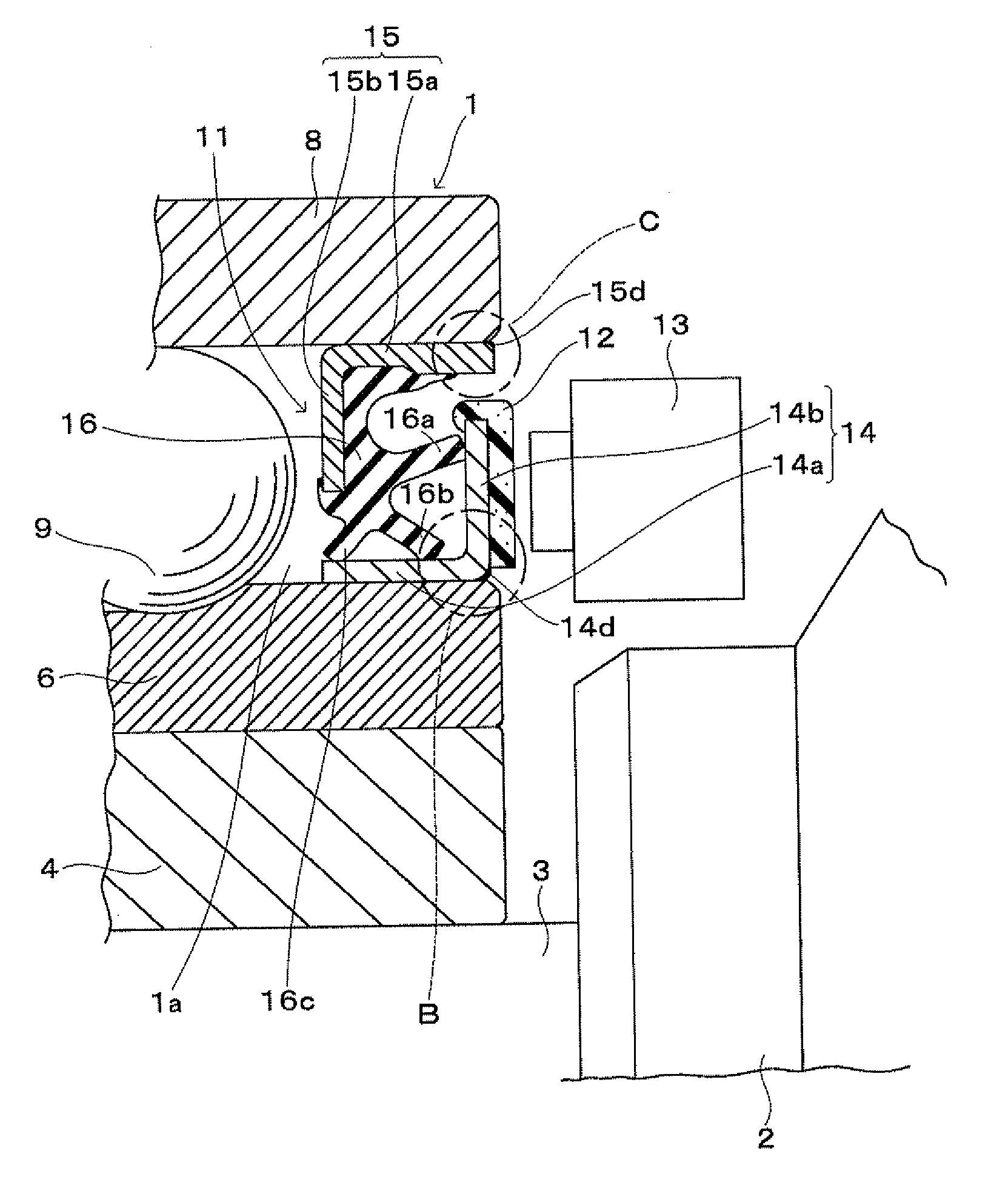
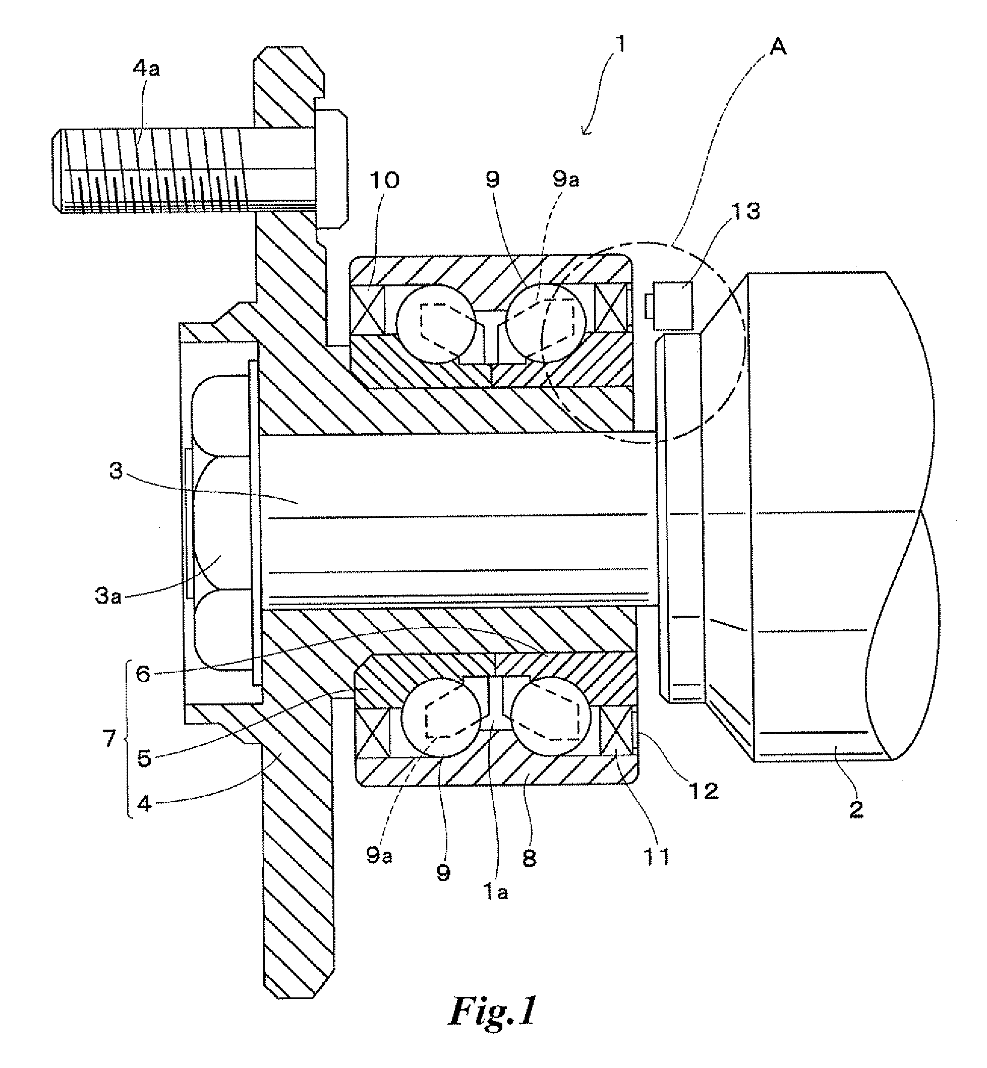
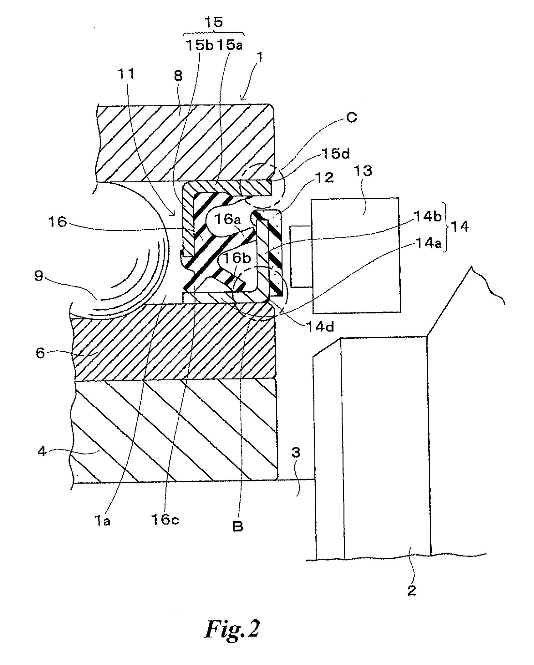
[0043]The metal slinger 14 and the inner ring member 6 which were fitted as shown in FIG. 3 were prepared, one-component-hardening silicone elastomer was discharged and applied by a dispenser to the external corner part 14c of the slinger 14 and was hardened by baking for 10 minutes at 150 degrees centigrade, and the annular seal layer 14d with thickness of 0.02 to 0.10 mm (mainly 0.04 mm) was formed. Then the slinger 14 was fitted to the inner ring member 6 as shown in FIG. 3. The fitting interference (radius value) was 0.02 to 0.15 mm. Scratch with depth of 0.02 mm along the axial direction was made on the fitting portion of the inner ring member 6, and the slinger 14 was similarly fitted in the same manner. When the fitting structure with scratch and one without scratch were rendered in an air leak experiment under pressurized environment, no air leak was caused even when the inner pressure was increased to no more than 0.4 MPa.

experimental example 2

[0046]Elastomeric agents with different viscosity were prepared, discharged and applied on an experimental piece by a dispenser, and the evaluation test was executed on the moldability of the annular seal layer in the process of hardening. FIG. 15 is a table of the evaluation test results. In FIG. 15, the moldability was visually evaluated based on whether the elastomeric agent flowed or not when the elastomeric agent was applied to a standing experimental piece, and whether sticky string was caused or not after the dispenser stops application and the nozzle was detached from the applied part. In the column of moldability evaluation, “×” indicates the flow and sticky string were shown and the annular seal layer became non-uniform enough to deteriorate the sealing ability. “◯” indicates the flow and sticky string were slightly shown, however, the annular seal layer obtained an expected sealing performance. “{circle around (o)}” indicates the flow and sticky string were not shown and ...


PUM


Abstract

A sealing structure for a fitting portion where an annular member is concentrically fitted to a cylindrical member to be fitted at a cylindrical part of the annular member is disclosed. The sealing structure is characterized by an elastic annular seal layer integrally provided on the backward end part of the annular member or the cylindrical member in fitting direction, by applying elastomeric agent to the backward end part and hardening it, and the elastic annular seal layer is formed such that it has layer thickness of 5 μm to 1 mm and is interposed in a compressed state between the annular member and the cylindrical member when said annular member is fitted to said cylindrical member.

Description

TECHNICAL FIELD[0001]The present invention relates to a sealing structure for a fitting portion, for example, to a sealing structure for a fitting portion of a slinger constituting an oil seal and a rotary side member of a bearing device.BACKGROUND ART[0002]For example, in an automotive bearing device, a slinger of which section is in the shape of the letter “L”, having a cylindrical part and a flange part extending from one end of the cylindrical part, is fitted to a rotary side member (an inner ring member, a drive shaft, and the like) from the other end of the cylindrical part in such a manner that the cylindrical part is fitted; and an oil seal (a bearing seal) is incorporated, the oil seal being constructed in such a manner that a seal lip of a seal lip member fitted to the stationary side member (an outer ring member) via a core member elastically contacts the surface of the cylindrical part opposite to the fitting portion and one surface of the extending flange part. In such ...

Claims


Application Information

Patent Timeline
Patent Type & Authority Applications(United States)
IPC IPC(8): F16J15/32F16J15/16F16C19/18F16C33/72F16C33/76F16C33/78F16C41/00F16J15/14F16J15/3232F16J15/326F16J15/3276
CPCF16J15/14F16J15/3264F16J15/3276F16C33/723F16C2326/02F16C33/7879F16C33/7886F16C41/007F16C33/768F16C19/184F16C19/186F16C33/783
Inventor YAMAMOTO, MASANORISHIBAYAMA, MASANORIKIYOSHI, TERUYUKI
Owner UCHIYAMA MFG
Learn More