
Gas analyzer for measuring at least two components of a gas

a gas analyzer and gas technology, applied in the direction of optical elements, optical radiation measurement, instruments, etc., can solve the problems of not being able to zero in normal operation, easy to be contaminated by mucus or condensed water, and no really compact multigas analyzer of the mainstream type has been commercially availabl

Active Publication Date: 2012-04-26
GENERAL ELECTRIC CO
View PDF7 Cites 21 Cited by
  • Summary
  • Abstract
  • Description
  • Claims
  • Application Information

AI Technical Summary

Benefits of technology

[0013]The above-mentioned shortcomings, disadvantages and problems are addressed herein which will be understood by reading and understanding the following specification.

Problems solved by technology

Because the measuring chamber is in the breathing circuit, it is easily contaminated by mucus or condensed water.
It is not possible to zero it during its normal operation.
Due to these requirements, only single gas analyzers for carbon dioxide CO2 have been available and no really compact multigas analyzers of the mainstream type have been commercially available.
However, this is difficult to accomplish using a multiple of discrete bandpass filters.
Either it would require a rotating filter wheel, which may be big and apt to mechanical damage, or a number of beam splitters to separate the different bandpass wavelengths to different detectors.
However, with discrete dielectric optical bandpass filters it does not seem to be possible to make an analyzer small enough to apply also for patients like small children and neonates.
It is an additional problem that the different respiratory gases have so widely spaced wavelength regions of absorption.
Therefore, such a single path solution would not be applicable.
Thus, this solution cannot be made more compact or faster than an analyzer using only a filter wheel to select the measurement wavelengths.
This makes measurements of multiple gases almost impossible unless the wavelength regions are close together.

Method used


Image

  • Gas analyzer for measuring at least two components of a gas
  • Gas analyzer for measuring at least two components of a gas
  • Gas analyzer for measuring at least two components of a gas

Examples


Embodiment Construction

[0023]Specific embodiments of the present invention are explained in the following detailed description making a reference to accompanying drawings. These detailed embodiments of the present invention can naturally be modified and should not limit the scope of the invention as set forth in the claims.

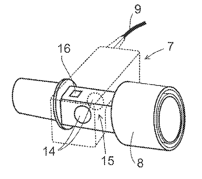
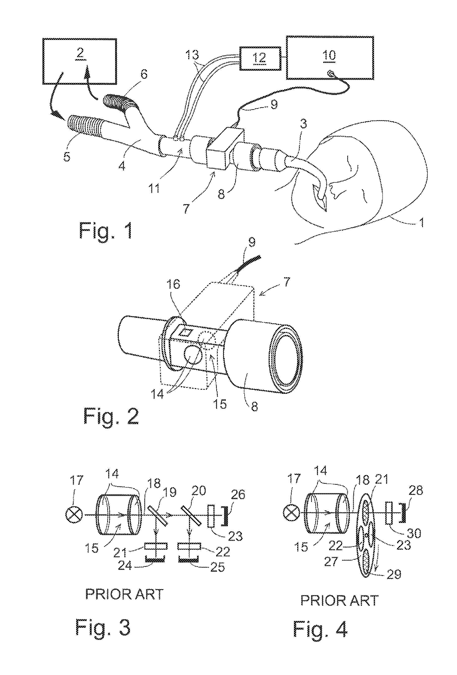
[0024]A gas analyzer for measuring at least two components of a gas such as a respiratory gas is described. An embodiment of the present invention can for instance be applied in clinical non-dispersive infrared multigas analyzers of mainstream type but it can also be applied in other types of respiratory gas analyzers and as well in gas analyzers to measure other gases than respiratory gases.

[0025]When measuring the patient gas, especially in neonatal and pediatric cases, it is crucial that the gas analyzer is fast, small and lightweight. A mainstream gas analyzer for only carbon dioxide and known in prior art can fulfill these criteria, but the problem arises when multiple gases are to...


PUM


Abstract

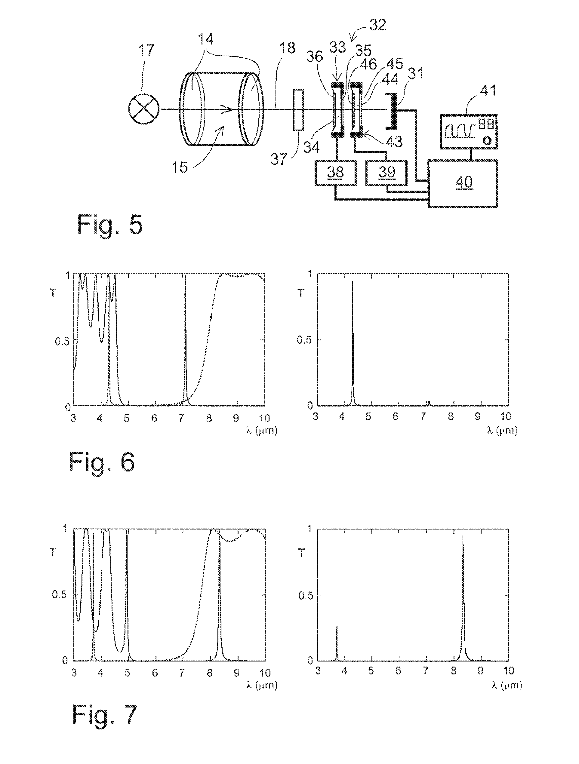
A gas analyzer for measuring at least two components of a gas is disclosed herein. The gas analyzer comprising an emitter configured to emit infrared radiation through the gas, a filter assembly configured to permit a transmission of predetermined wavelengths emitted by the emitter, and a detector configured to receive wavelengths emitted by the emitter and penetrated through the filter assembly. The filter assembly comprises at least two tunable narrowband interference filters in series, each of the filters comprising two dielectric mirrors and an air space between the two dielectric mirrors to tune one of the filters to different transmission band than another of the filters.

Description

BACKGROUND OF THE INVENTION[0001]1. Field of the Invention[0002]The field of the invention relates to a gas analyzer for measuring at least two components of a gas. The gas analyzer comprises an emitter for being able to emit infrared radiation through the gas, a filter assembly for allowing a transmission of predetermined wavelengths emitted by the emitter, and a detector for receiving wavelengths emitted by the emitter and penetrated through the filter assembly.[0003]2. Description of Related Art[0004]In anesthesia or in intensive care, the condition of a patient is often monitored e.g. by analyzing the gas exhaled by the patient for its content. For this reason either a small portion of the respiratory gas is delivered to a gas analyzer or the gas analyzer is directly connected to the respiratory circuit. In a non-dispersive infrared (NDIR) gas analyzer the measurement is based on the absorption of infrared (IR) radiation in the gas sample. A radiation source directs a beam of in...

Claims


Application Information

Patent Timeline
IPC IPC(8): G01N21/17G01J5/10
CPCG01N21/314G01N21/3504G01N33/497G02B5/284G01N2021/3177G01N2021/3185G01N2021/3137
Inventor WECKSTROM, KURT PETERMIKAEL HAVERI, HEIKKI ANTTI
Owner GENERAL ELECTRIC CO
Learn More