
Device for centering an air inlet structure on a central structure of a nacelle

a technology of air inlet structure and central structure, which is applied in the direction of measurement devices, aircraft components, instruments, etc., can solve the problems of reducing performance, specific tools not always enabling satisfactory monitoring, and insufficient holes, etc., to reduce cost and production time, reduce jamming, and reduce jamming.

Inactive Publication Date: 2012-04-26
SAFRAN NACELLES
View PDF5 Cites 2 Cited by
  • Summary
  • Abstract
  • Description
  • Claims
  • Application Information

AI Technical Summary

Benefits of technology

[0013]One aim of the present invention is therefore to provide an effective centering device that is easy to implement and makes it possible to avoid any risk of jamming, in the aforementioned particular case of an air inlet structure that is mobile relative to a median nacelle structure, but also in the more general case of any structure that is mobile relative to a stationary nacelle structure.

Problems solved by technology

This frost formation can be dangerous for the mechanical operation of the stationary and rotating portions of the turbojet engine and cause a decrease in performance.
However, these holes are not always sufficient.
It is thus sometimes necessary to verify the internal equipment of the air inlet structure using specific tools, such as an endoscope.
Such specific tools do not always enable a satisfactory monitoring.
Such a placement requires significant tools and causes an immobilization of the propulsive assembly and therefore generally of the airplane.
Such a configuration causes a relatively high production cost.

Method used


Image

  • Device for centering an air inlet structure on a central structure of a nacelle
  • Device for centering an air inlet structure on a central structure of a nacelle
  • Device for centering an air inlet structure on a central structure of a nacelle

Examples


first embodiment

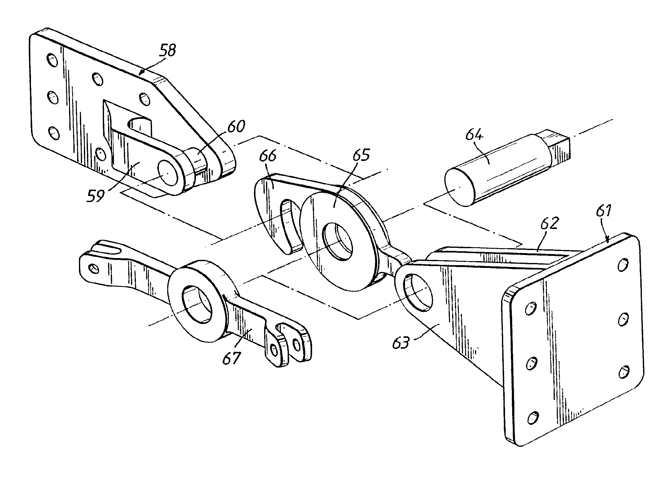
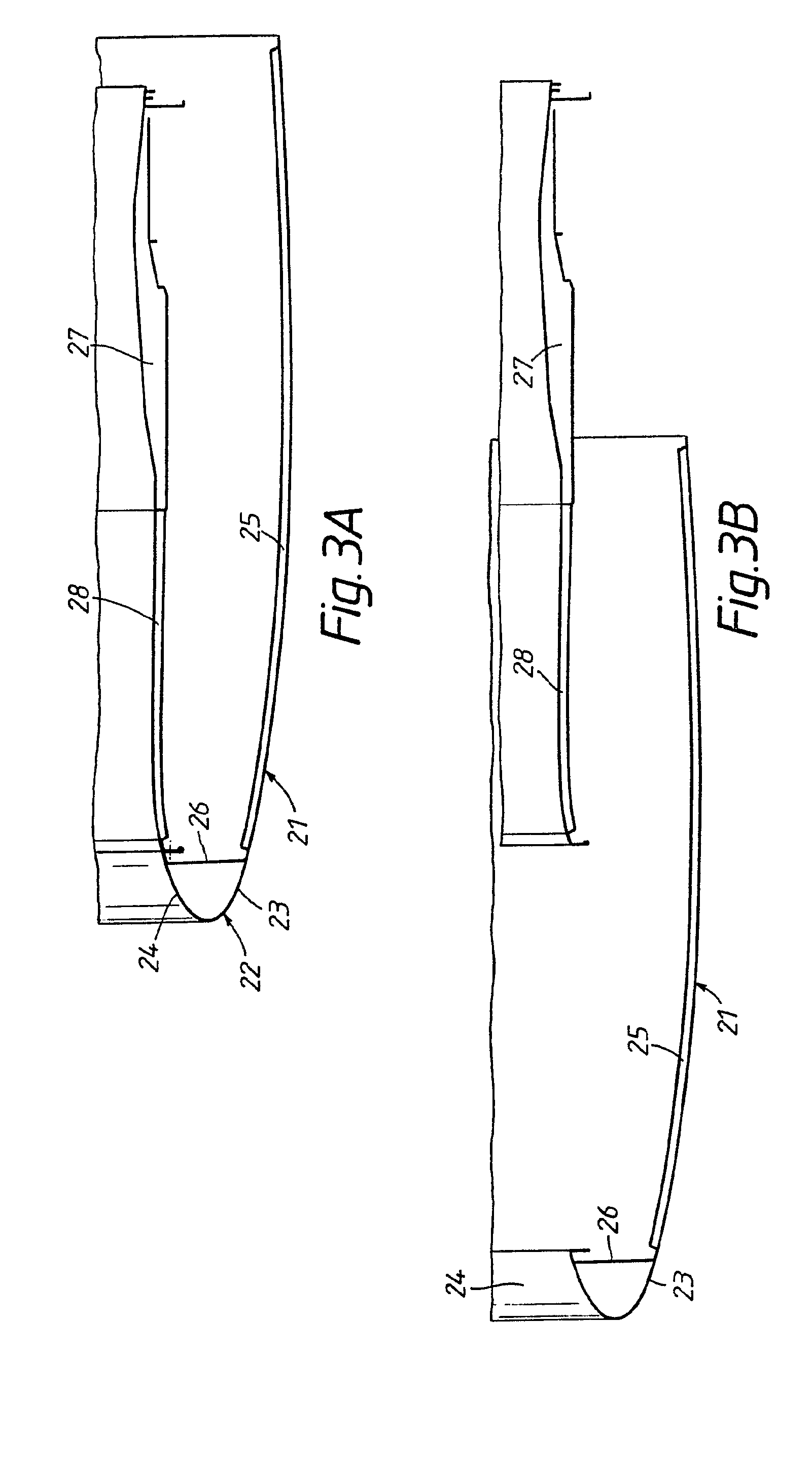
[0066]FIGS. 3a and 3b show the device 50 according to the invention. More particularly, FIG. 3a illustrates a configuration in which the centering pin 52 is not inserted into the receiving bore 60. FIG. 3b illustrates a configuration in which the centering pin 52 is inserted into the receiving bore 60.

[0067]In this embodiment, the interface system 70 is mounted in the receiving bore 60 while having reduced play relative to the play inherent to the machining of the interface system 70 and the receiving bore 60. The interface system 70 is in the form of a disc 90 having a central orifice 71 with a diameter substantially equal to that of the centering pin 52. The central orifice 71 and the interface system can have a combined central axis.

[0068]The play being reduced to its minimum, it makes it possible to ensure good geometric positioning of the centering pin 52 relative to the receiving bore 60. Such a configuration makes it possible to avoid any adjustment or blocking to the install...

second embodiment

[0076]FIGS. 4a and 4b show the device 50 of the invention. More particularly, FIG. 4a illustrates a configuration in which the centering pin 52 is not inserted into the receiving bore 60. FIG. 4b illustrates a configuration in which the centering pin 52 is inserted in the receiving bore 60.

[0077]According to this alternative, the interface system 70 includes a ball pivot 100 mounted in the central orifice 71 of the receiving bore 60, in particular the disc 90. In the case where the ball pivot 100 is inserted into the disc 90, the wall of the central portion 96 is thinned so as to have a central orifice 71 with a diameter substantially equal to that of the centering pin 52.

[0078]Thus, any relative misalignment between the central axes 56 and 72, but also between any other centering devices installed on the periphery of the nacelle 1 of the invention, are absorbed. Because of this, this type of alignment does not harm the centering of the air inlet structure 4 on the median structure ...

third embodiment

[0080]FIGS. 5a and 5b show the device 50 according to the invention. More particularly, FIG. 5a illustrates a configuration in which the centering pin 52 is not inserted into the receiving bore 60. FIG. 5b illustrates a configuration in which the centering pin 52 is inserted into the receiving bore 60.

[0081]According to this other alternative, the centering pin 52 is mounted on a ball pivot 111 fastened in the pin holder 54. In this configuration, the ball pivot has a standard design, the angular displacement limitation of the pin being picked up by the surrounding mechanical parts.

[0082]FIGS. 6a and 6b show still another embodiment of the device 50 according to the invention. More particularly, FIG. 6a illustrates a configuration in which the centering pin 52 is not inserted into the receiving bore 60. FIG. 6b illustrates a configuration in which the centering pin 52 is inserted into the receiving bore 60.

[0083]According to this alternative, the interface system 70 is mounted on th...


PUM


Abstract

The invention relates to a device (50) for centering a movable structure (4) on a stationary structure (5) of a nacelle, comprising: a centering pin (52) mounted on a pin holder (54) attached onto the movable structure (4) or onto the stationary structure (5), the centering pin (52) having a central axis (56) and a receiving bore (60) mounted onto a bore holder (62) attached onto the stationary structure (5) or onto the movable structure (4), said receiving bore (60) being capable of receiving at least the centering pin (52), characterized in that the centering device (50) also comprises a movable interface system, capable of overlapping the central axis (56) of the centering pin (52) and the central axis of said interface system or of the receiving bore (60) and capable of receiving said centering pin (52) in a central opening, and a locking means capable of locking said interface system. The invention also relates to a nacelle including such a device (50).

Description

TECHNICAL FIELD[0001]The invention relates to a device for centering an air inlet structure on a median structure of a nacelle.[0002]The invention also relates to a nacelle comprising such a centering device.BACKGROUND[0003]In general, an aircraft nacelle has a structure comprising an air inlet structure, a median structure and a downstream structure. The term “downstream” here refers to the direction corresponding to the direction of the cold air flow penetrating the turbojet engine. The term “upstream” refers to the opposite direction.[0004]The nacelle has a downstream jet nozzle whereof the outlet is situated downstream of the turbojet engine. Further upstream, the downstream section generally houses thrust reverser means intended to surround the combustion chamber of the turbojet engine. The median structure is positioned downstream of the air inlet structure so as to surround the fan of the turbojet engine. The air inlet structure is situated upstream of the turbojet engine ser...

Claims


Application Information

Patent Timeline
IPC IPC(8): G01D21/00
CPCF16B19/02B64D29/06
Inventor VAUCHEL, GUY BERNARD
Owner SAFRAN NACELLES
Learn More