


Quick Research
Generate reliable direction feasibility study reports for your R&D in just a few steps.

Technical Q&A
Discover and master advanced knowledge NOW. Basics, ideas, possibilities, all at once.

Find Solutions
As an expert in R&D theories, this can generate solutions to your technical problems instantly.

Evaluate Feasibility
Analyze your overall solution with one click, know your potential R&D risks in advance.

Monitor Landscape
Get weekly tech updates, stay abreast of the latest tech innovations and key insights.
Illuminating device, display device, and television receiver
a technology for illuminating devices and television receivers, which is applied in the direction of lighting support devices, lighting and heating apparatus, instruments, etc., can solve the problems of increasing the cost of backlight units, reducing the light emission efficiency of leds, and complicating the manufacturing process of backlight units, so as to facilitate the manufacturing of illuminating devices
- Summary
- Abstract
- Description
- Claims
- Application Information
AI Technical Summary
Benefits of technology
Problems solved by technology
Method used
Image

Examples
embodiment 1
[0071]The present invention will be described below by way of embodiments with reference to the accompanying drawings. For convenience' sake, hatching and reference signs are occasionally omitted, in which case reference is to be made to any other relevant drawing; also for convenience' sake, hatching is occasionally used elsewhere than in a sectional view.
[0072]FIG. 17 shows an LCD (liquid crystal display) television 89 incorporating a liquid crystal display device (display device) 69. The LCD television 89 receives a television broadcast signal and displays an image; thus, the LCD television 89 is a television receiver. FIG. 16 is an exploded perspective view showing the liquid crystal display device. As shown there, the liquid crystal display device 69 includes a liquid crystal display panel (display panel) 59, a backlight unit (illuminating device) 49 which supplies light to the liquid crystal display panel 59, and a housing HG in which (a front housing HG1 and a rear housing HG...
embodiment 2
[0128]A second embodiment will now be described. Such members as find their functional counterparts in Embodiment 1 are identified by the same reference signs, and no overlapping description will be repeated.
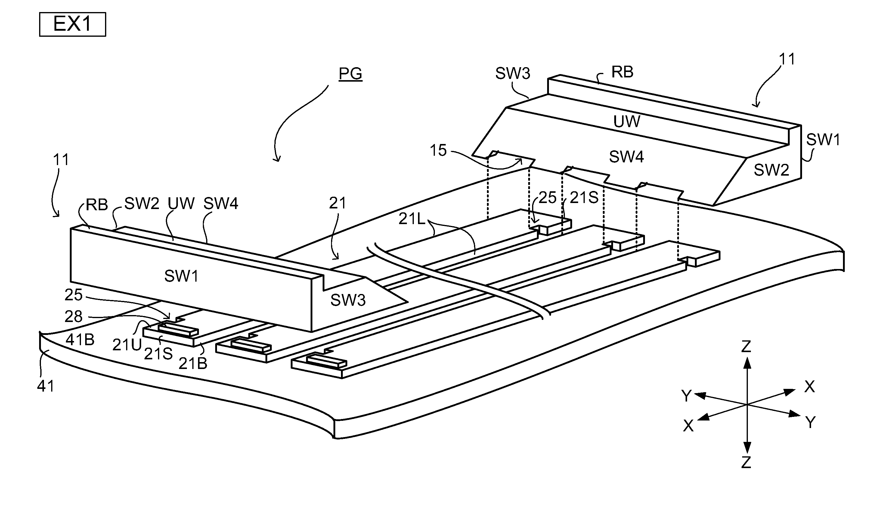
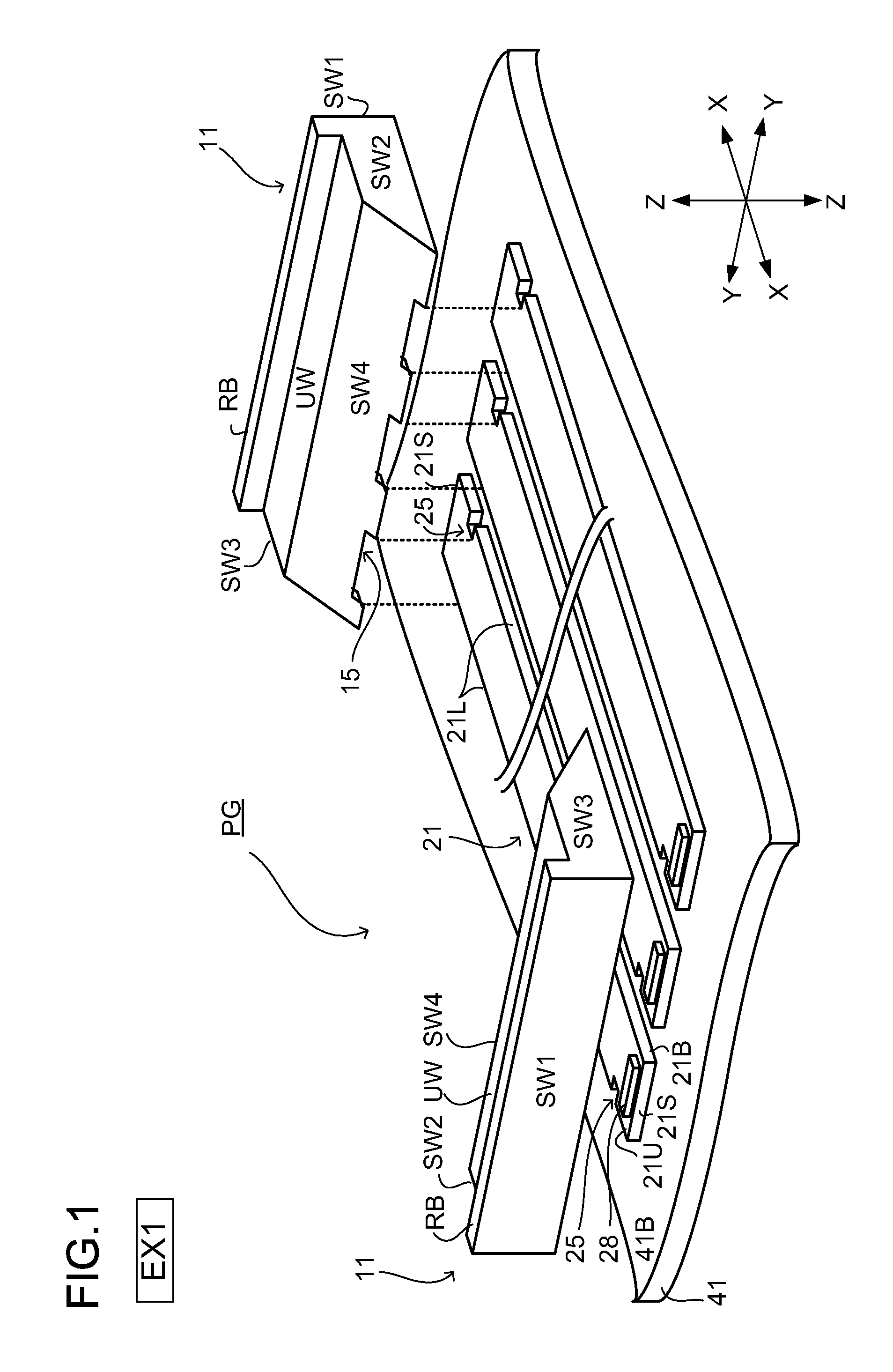
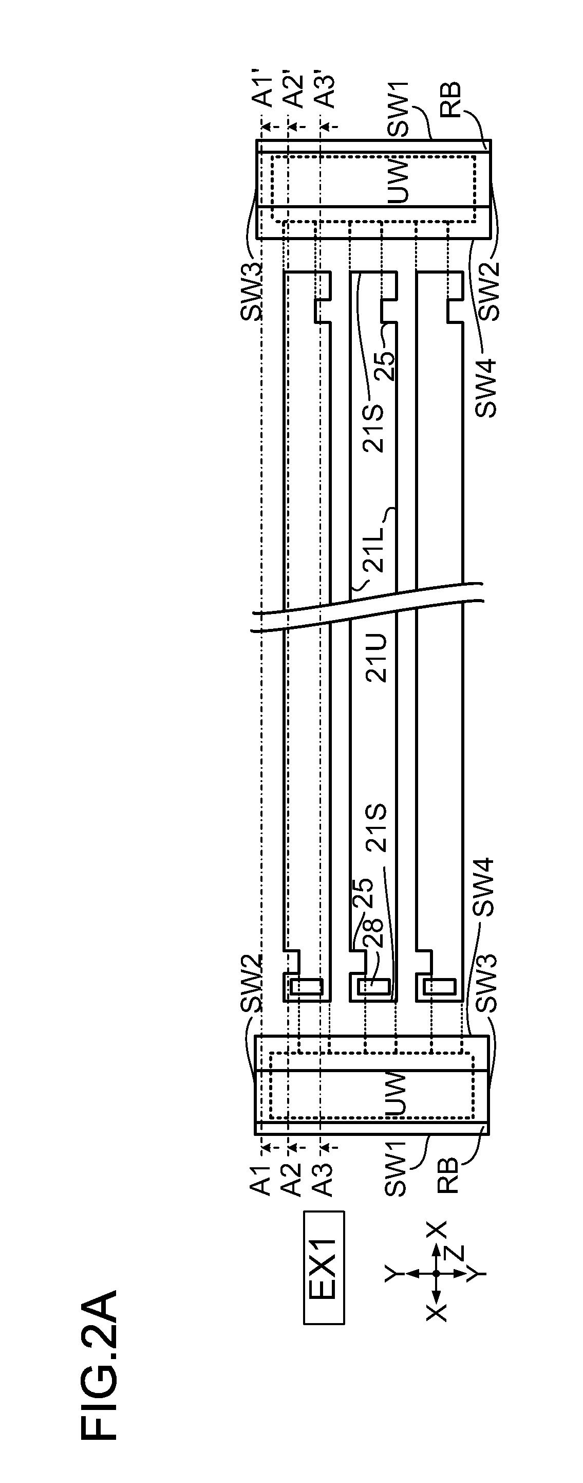
[0129]In Embodiment 1, the board-side cut 25 is formed as an indentation that is made only from a longer-side edge 21L of the mounting board 21. This, however, is not meant as any limitation. For example, as shown in FIGS. 5A to 5C, the board-side cut 25 may be formed as an indentation that is made both from a longer-side edge 21L and from a shorter-side edge 21S. Specifically, the board-side cut 25 may have an L-shaped contour.
[0130]Such a board-side cut 25 will now be described with reference to FIGS. 5A to 5C and 6A to 6C (the backlight unit 49 shown in these diagrams is dealt with as a second embodiment (EX 2)). FIGS. 5A to 5C are views similar to FIGS. 2A to 2C respectively.
[0131]FIG. 6A is a sectional view along line B1-B1′ in FIGS. 5A to 5C as seen from the arrow-indicate...
embodiment 3
[0145]A third embodiment will now be described. Such members as find their functional counterparts in Embodiments 1 and 2 are identified by the same reference signs, and no overlapping description will be repeated.
[0146]In Embodiments 1 and 2, the board-side cut 25 is formed in the longer-side edge 21L of the mounting board 21. This, however, is not meant as any limitation. For example, the board-side cut 25 may be formed as an indentation that is made from the shorter-side edge 21S of the mounting board 21.
[0147]Such a board-side cut 25 will now be described with reference to FIGS. 8A to 8C and 9C to 9C (the backlight unit 49 shown in these diagrams is dealt with as a third embodiment (EX 3)). FIGS. 8A to 8C are views similar to FIGS. 2A to 2C respectively.
[0148]FIG. 9A is a sectional view along line C1-C1′ in FIGS. 8A to 8C as seen from the arrow-indicated direction. FIG. 9B is a sectional view along line C2-C2′ in FIGS. 8A to 8C as seen from the arrow-indicated direction. FIG. 9C...
PUM
| Property | Measurement | Unit |
|---|---|---|
| reflectance | aaaaa | aaaaa |
| reflectance | aaaaa | aaaaa |
| reflection | aaaaa | aaaaa |
Abstract
Description
Claims
Application Information
 - R&D Engineer
- R&D Manager
- IP Professional
- Industry Leading Data Capabilities
- Powerful AI technology
- Patent DNA Extraction
Browse by: Latest US Patents, China's latest patents, Technical Efficacy Thesaurus, Application Domain, Technology Topic, Popular Technical Reports.
© 2024 PatSnap. All rights reserved.Legal|Privacy policy|Modern Slavery Act Transparency Statement|Sitemap|About US| Contact US: help@patsnap.com