High elongation fibres

a high-elongation, fibre technology, applied in the direction of magnet bodies, manufacturing tools, cores/yokes, etc., can solve the problems of low post-crack strength ratio between ultimate limit state (uls) and service-ability limit state (sls), and low performance at ultimate state (uls)

Active Publication Date: 2012-04-19
NV BEKAERT SA
View PDF19 Cites 7 Cited by
  • Summary
  • Abstract
  • Description
  • Claims
  • Application Information

AI Technical Summary

Benefits of technology

[0014]It is another object of the present invention to provide a new type of steel fibres which are taking loads in structural applications without requiring high dosages.
[0039]The higher degree of anchorage of the steel fibres in the concrete or mortar, the higher the residual strength of the concrete or more. The better the steel fibres are prevented from slipping out of the concrete, the better the full strength of the middle portion of the steel fibre is used. For example in case the anchorage force of the steel fibre in the concrete or mortar is 90%; 90% of the full strength of the middle portion of the steel fibre may be used.

Problems solved by technology

The disadvantage today with these fibres is their relatively low performance at ultimate state (ULS).
Especially, the ratio between ultimate limit state (ULS) and service-ability limit state (SLS) post-crack strength is relatively low.
Some prior art fibres do not perform at ULS as they break at CMOD lower than what is required for ULS.
The huge dosages can cause workability problems such as the mixing and placing problems.

Method used


Image

  • High elongation fibres
  • High elongation fibres
  • High elongation fibres

Examples


Embodiment Construction

[0054]The present invention will be described with respect to particular embodiments and with reference to certain drawings but the invention is not limited thereto but only by the claims. The drawings described are only schematic and are non-limiting. In the drawings, the size of some of the elements may be exaggerated and not drawn on scale for illustrative purposes. The dimensions and the relative dimensions do not correspond to actual reductions to practice of the invention.

[0055]The following terms are provided solely to aid in the understanding of the inventions.

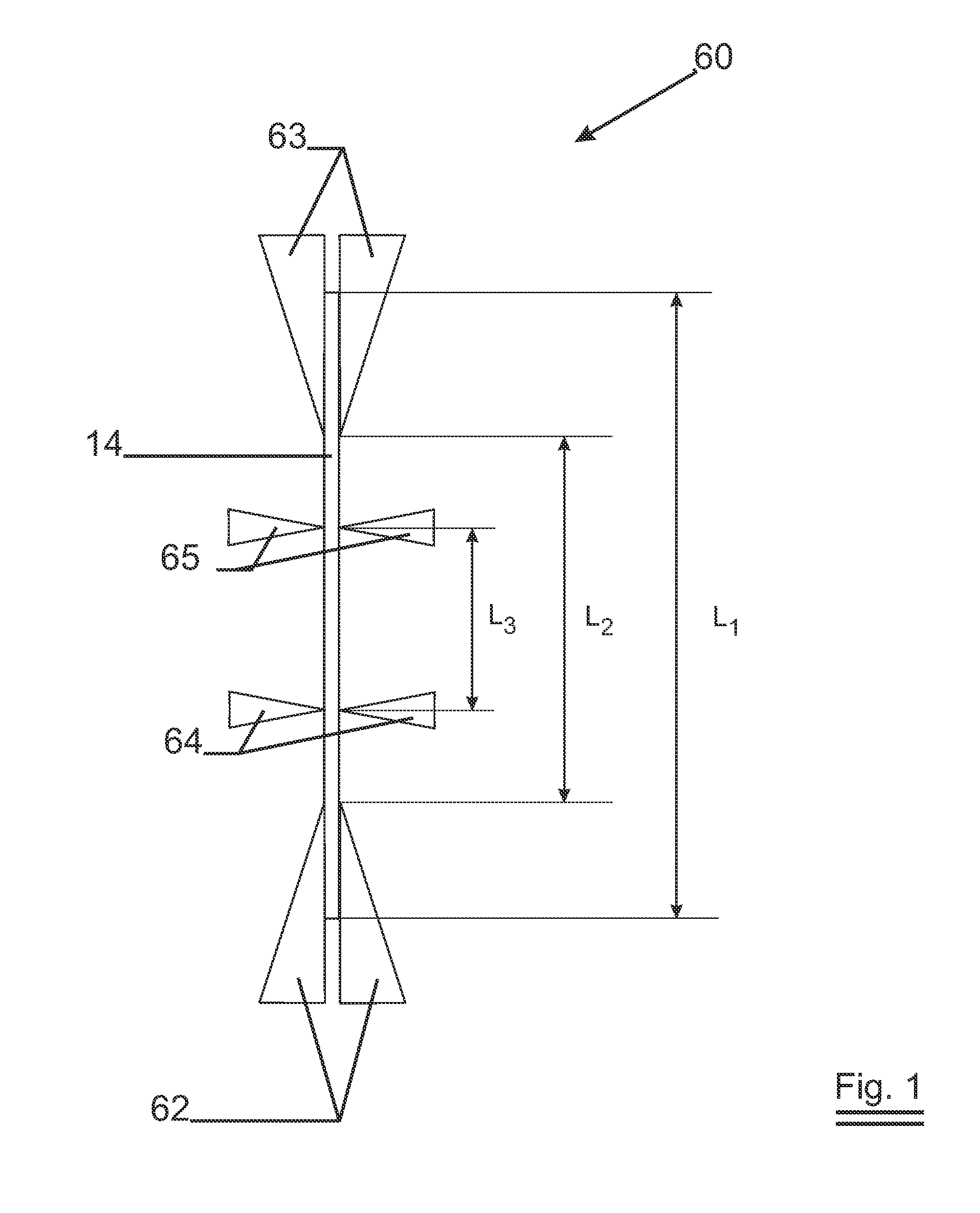
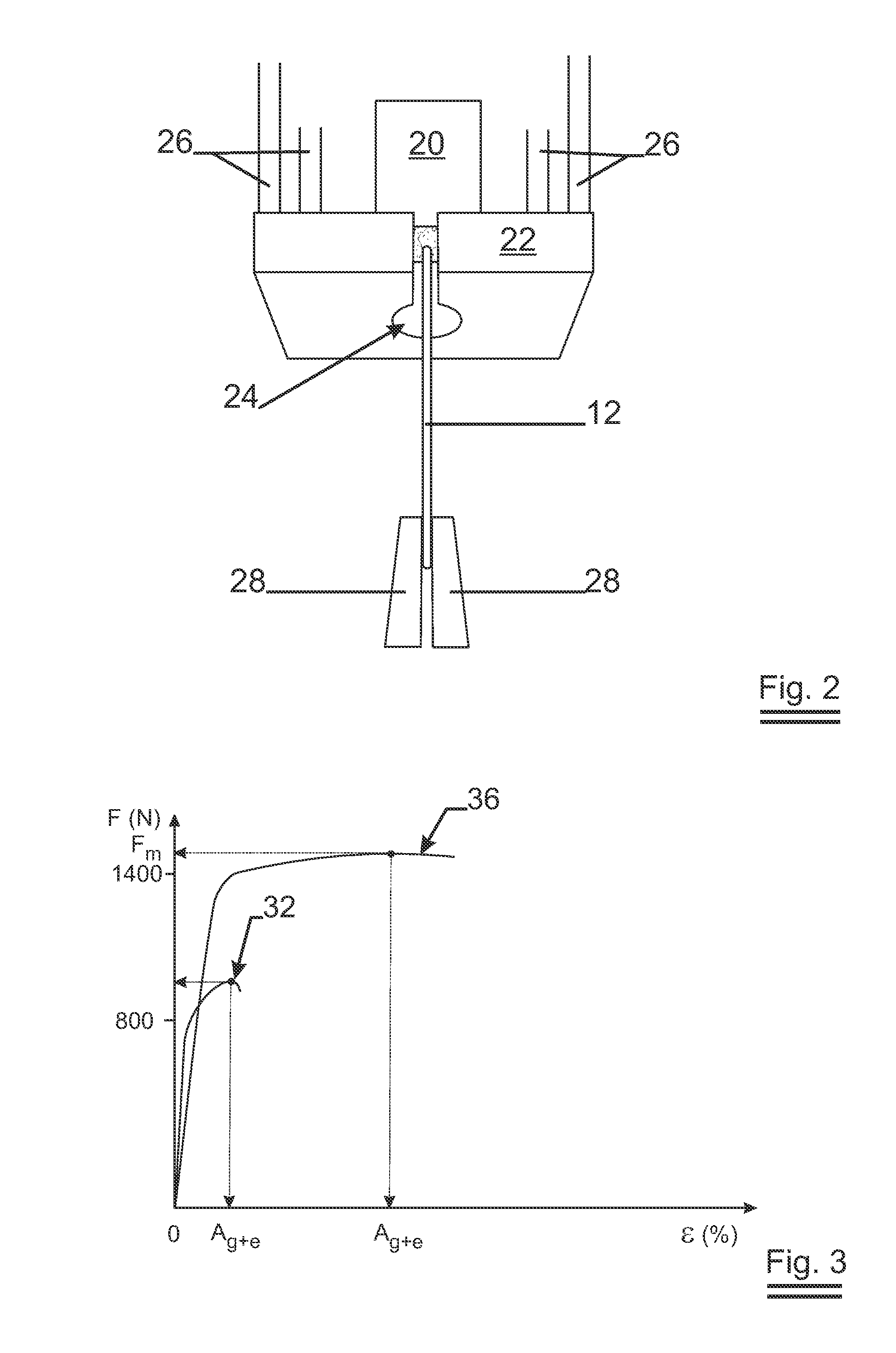
[0056]Maximum load capacity (Fm): the greatest load which the steel fibre withstands during a tensile test;

[0057]Elongation a maximum load (%): increase in the gauge length of the steel fibre at maximum force, expressed as a percentage of the original gauge length;

[0058]Elongation at fracture (%): increase in the gauge length at the moment of fracture expressed as a percentage of the original gauge length;

[0059]Tensile...


PUM

PropertyMeasurementUnit
elongationaaaaaaaaaa
tensile strength Rmaaaaaaaaaa

Abstract

The invention relates to a steel fibre for reinforcing concrete or mortar. The fibre has a middle portion and two ends. The middle portion has a ensile strength of at least 1000 N and an elongation at maximum load Ag+e of at least 2.5%. The invention further relates to a concrete structure comprising such steel fibres.

Description

TECHNICAL FIELD[0001]This invention relates to a new type of steel fibre adapted for reinforcing mortar or concrete and in particular for reinforcing conventional concrete.[0002]The steel fibres are characterized by a high elongation.[0003]The invention also relates to a structure of conventional concrete reinforced with this type of steel fibres.[0004]Furthermore, the invention relates to the use of this type of steel fibres for reinforcement of conventional concrete, reinforced, pre-stressed or post-tensioned concrete.BACKGROUND ART[0005]It is well-known to reinforce concrete or mortar with steel fibres to improve the quality of the concrete or mortar. Steel fibres are for example used to reinforce conventional concrete.[0006]The term “conventional concrete” refers to a concrete having a compression strength lower than 75 MPa (1 MPa=1 Mega-Pascal=1 Newton / mm2), e.g. lower than 70 MPa, and preferably lower than 60 MPa.[0007]EP-B1-851957 (NV Bekaert SA) teaches a steel fibre with fl...

Claims


Application Information

Patent Timeline
Patent Type & Authority Applications(United States)
IPC IPC(8): C04B14/48E04C5/01
CPCE04C5/012Y10T428/12Y10T428/1241Y10T428/12389C04B14/48
Inventor LAMBRECHTS, ANN
Owner NV BEKAERT SA
Why Eureka
Try Eureka