
Modular system having expandable form factor

Active Publication Date: 2012-04-12
COMPAL ELECTRONICS INC
View PDF5 Cites 167 Cited by
  • Summary
  • Abstract
  • Description
  • Claims
  • Application Information

AI Technical Summary

Benefits of technology

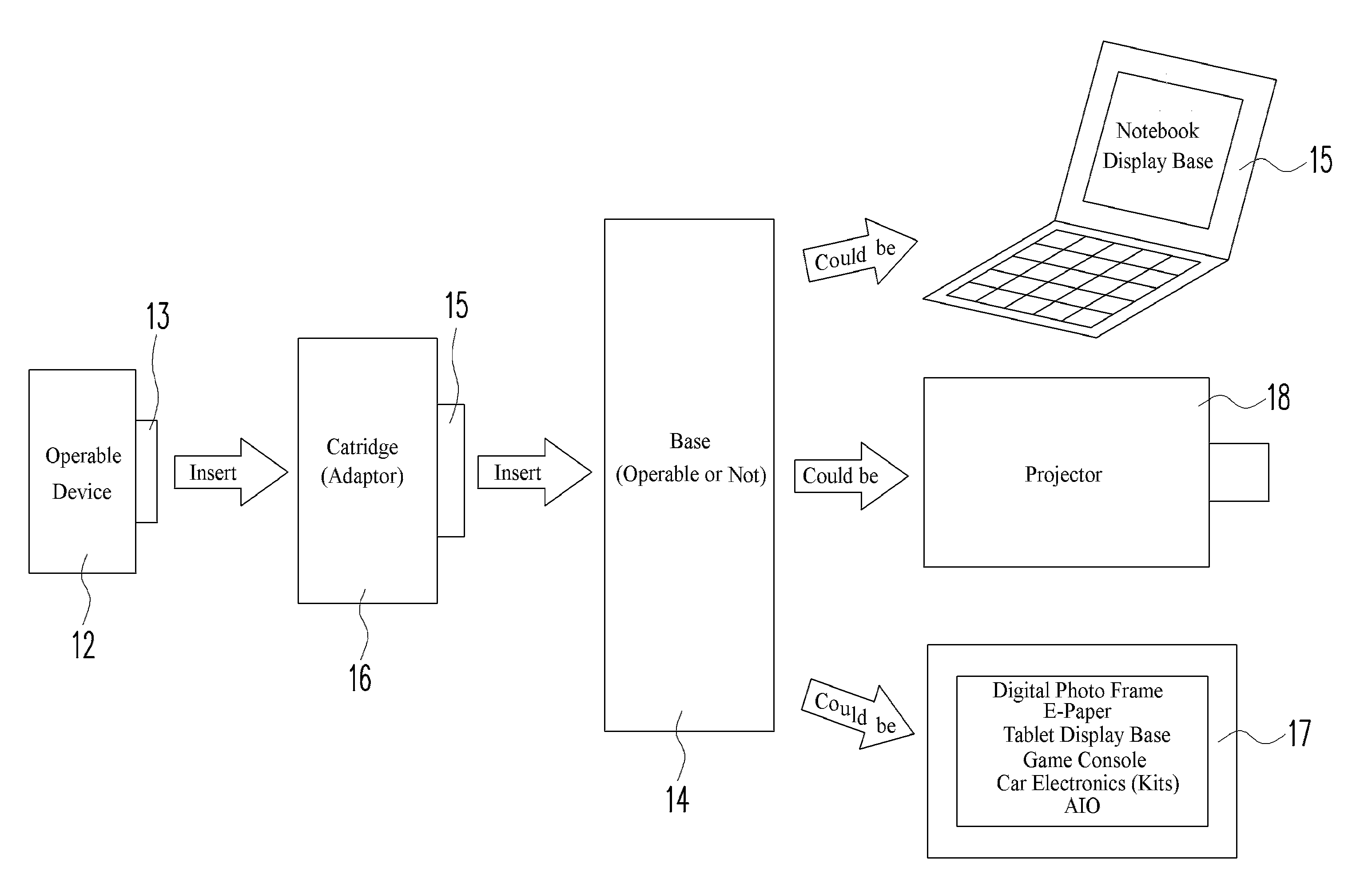
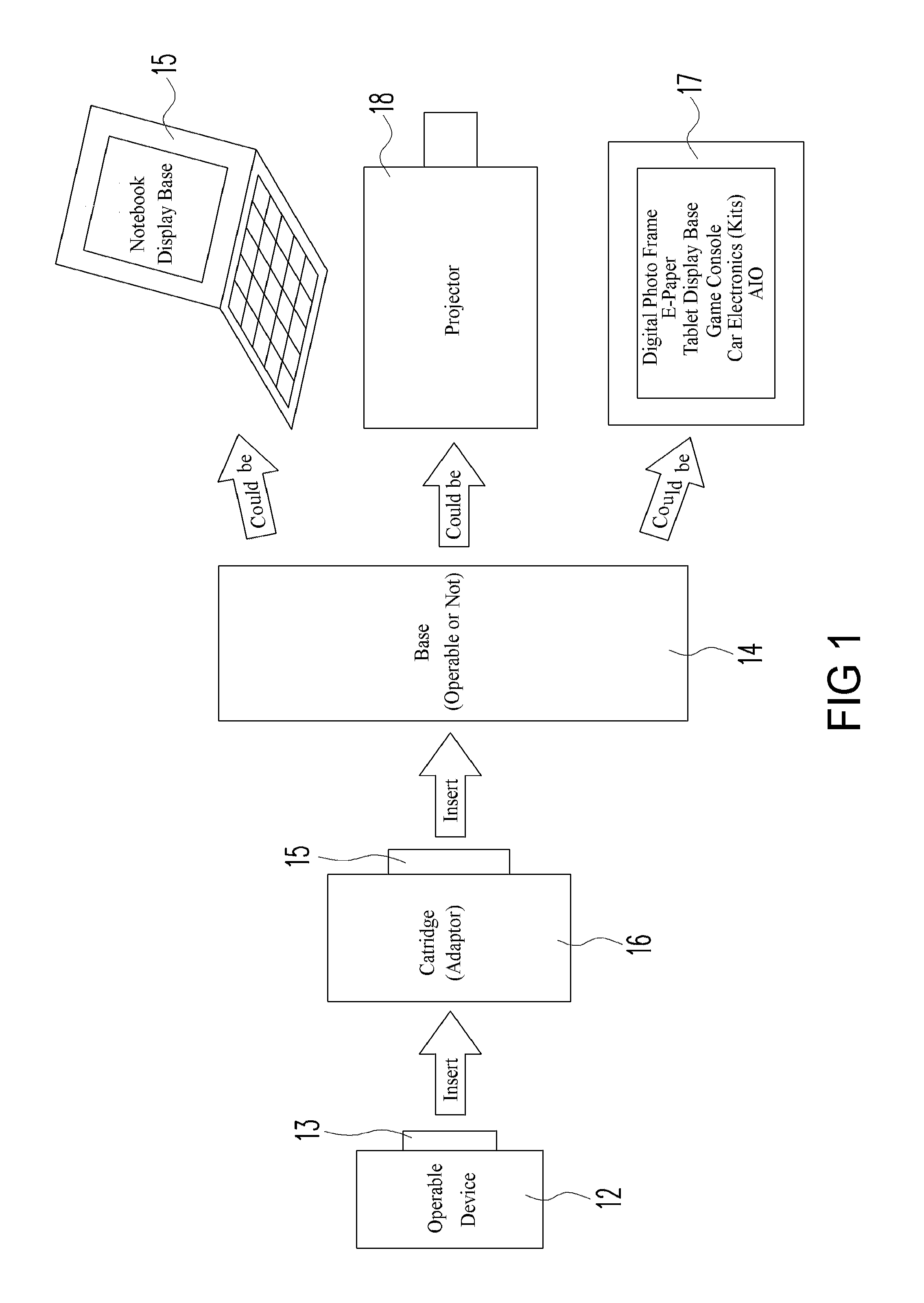
[0011]The present invention provides a modular system of devices, in which a (master) device can be combined with one or more of the other (slave) devices in the system to transform to functional electronic devices (e.g., handheld cellular phone, tablet computing device, notebook PC device, netbook device, etc.) having expanded functionalities and features in expanded form factors and / or different platforms. The modular system reduces redundancy among the components of the various devices in the system, and instead improves operability with optimized and / or enhanced functionalities and features, as the master device transforms to a larger form factor and / or a different platform by combining with a slave device. When the master device transformed from one form factor and / or platform into another by combining with one or more slave devices, the master device provides control and / or stored data to operate the slave devices. The master device and slave devices share certain control, hardware, software and data, to reduce redundancy between devices of various form factors and / or platform, in a manner that provides additional or different functions and features in an optimized and / or enhanced manner as the form factor and / or platform changes from one to another. The master device is docked to different slave devices via a physical port or interface and a data / electrical port or interface, to complete different functional electronic devices of different form factors and / or platform, to achieve enhanced functionalities or a different set of functionalities.
[0018]In one embodiment, the physical interface adaptor is configured in the form of a cartridge, having a case that substantially encloses the master device. The cartridge has an external shape and size that conforms to the profile of the docking bay in the slave device. In another embodiment, the physical interface adaptor comprises a frame supporting the master device. The frame is structured with an internal profile conforming to at least a part of the master device housing, and an external form factor sized and shaped to directly fit inside the docking bay in the slave device housing. In another embodiment, the physical interface adaptor further comprises an adaptor bar removably coupled to the frame, wherein the adaptor bar supports an electrical adaptor. In a further embodiment, the physical interface adaptor further comprises a cartridge receiving the frame, and supporting the adaptor bar if one is provided. In this embodiment, the frame provides a thinner form-fitting intermediate structure that closely conforms to the external profile of master device, and the inside of the cartridge. The frame is a simpler structure (hence cheaper to make), which can be provided for each different master device having a different external profile, for compatibility with a cartridge having a more elaborate structure (hence more expensive to make) for a particular slave device. In other words, the cartridge can be made universal for docking to a particular slave device, but different frames can be configured to fit different master devices for the same cartridge.
[0019]In one embodiment of the present invention, the master device is configured to switch control of the slave device in a “hot swap” manner, without requiring power down of the master device and / or the slave device.

Problems solved by technology

Such limited, specific processing may be required for operations of specific peripherals in the larger slave device, such as I / O drivers, graphics drivers, human interface devices, etc, or other limited operation control functions for the peripheral components uniquely associated with the particular slave device (e.g., in the case of the slave device being an image projector device, the slave device may have limited processing control of the projection mechanism and power management).

Method used


Image

  • Modular system having expandable form factor
  • Modular system having expandable form factor
  • Modular system having expandable form factor

Examples


Embodiment Construction

[0049]The present description is of the best presently contemplated mode of carrying out the invention. This invention has been described herein in reference to various embodiments and drawings. This description is made for the purpose of illustrating the general principles of the invention and should not be taken in a limiting sense. It will be appreciated by those skilled in the art that variations and improvements may be accomplished in view of these teachings without deviating from the scope and spirit of the invention. The scope of the invention is best determined by reference to the appended claims.

[0050]Reference will now be made in detail to embodiments, examples of which are illustrated in the accompanying drawings. In the following detailed description, numerous specific details are set forth in order to provide a thorough understanding of the present invention. However, it will be apparent to one of ordinary skill in the art that the present invention may be practiced wit...


PUM


Abstract

A modular system of devices, in which a (master) device can be combined with one or more of other (slave) devices to transform to functional electronic devices having expanded functionalities and features in different form factors and / or platforms. The master device is docked to the slave device via a data / electrical interface, to transform the master device to the larger form factor of the slave device, with the master device maintaining control of the slave device, substantially based on the operating system installed in the master device, with access to the data, application programs, functionalities and features embodied in the master device. An intermediate removable physical interface adaptor (or docking adaptor) is provided to facilitate docking compatibility of the master device to the slave device. An enhanced charging and power management scheme is provided to optimize power management for the master device and the slave device.

Description

CROSS REFERENCE[0001]This application claims the priority of (a) U.S. Provisional Patent Application No. 61 / 404,696, filed on Oct. 6, 2010; (b) U.S. Provisional Patent Application No. 61 / 458,701, filed on Nov. 29, 2010; and (c) U.S. Provisional Patent Application No. 61 / 467,378, filed on Mar. 24, 2011; which are fully incorporated by reference as if fully set forth herein.BACKGROUND OF THE INVENTION[0002]1. Field of the Invention[0003]The present invention is directed to a modular system of devices, in which a master device can be combined with one or more of the other devices in the system to expand functionalities and features in different form factors and / or platforms.[0004]2. Description of Related Art[0005]The evolution of portable personal electronic devices changed the life of consumers. For example, notebook computers, cellular phones, etc., provided utility and convenience to consumers which are not possible just 20 years ago. Some of the smaller portable electronic devices...

Claims


Application Information

Patent Timeline
IPC IPC(8): G06F1/16H02J7/00
CPCH02J7/0054G06F1/1632G06F1/26G06F13/14H02J7/342
Inventor MEDICA, JOHNTSAI, LEONARDCHEN, SHIKUAN
Owner COMPAL ELECTRONICS INC
Learn More