
Fish tape leader with quick change coupling

a technology of leader and fish tape, which is applied in the direction of cables, snap fasteners, manufacturing tools, etc., can solve the problems of insufficient tightness of the tape inside the leader, and the installation of both systems takes a substantial amount of time, so as to save time and money

Inactive Publication Date: 2012-04-05
DAVIDSON SCOTT +1
View PDF2 Cites 11 Cited by
  • Summary
  • Abstract
  • Description
  • Claims
  • Application Information

AI Technical Summary

Benefits of technology

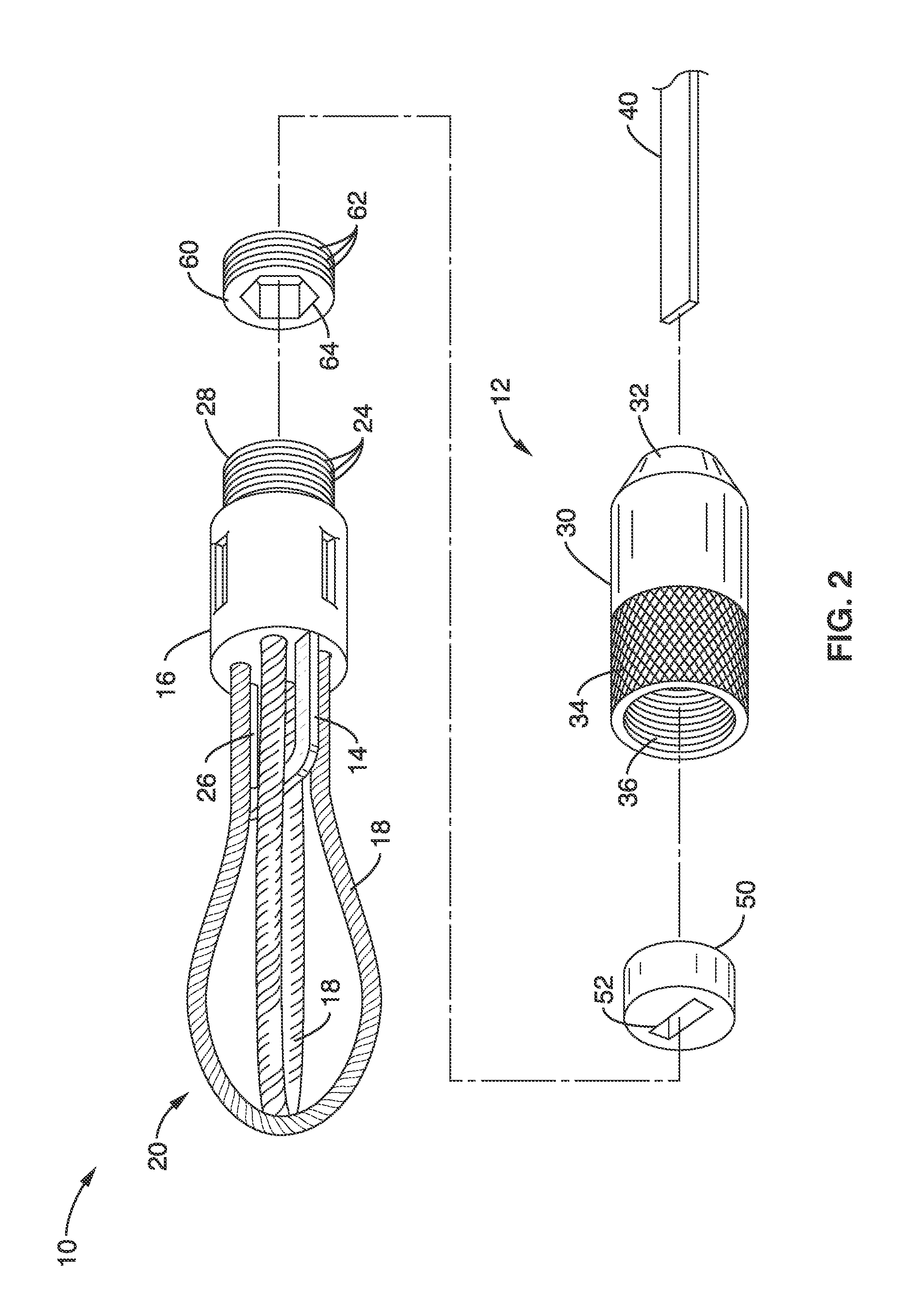
[0011]The leader system of the present invention incorporates a small adaptor is placed inside of the leader, which eliminates the need for solder or a tight loop on the end of the tape. The leader is placed on the tape and the adaptor slides onto the tape and sits inside of the leader. With two pairs of pliers placed with about a ⅛″ gap between them, a quarter turn (approximately a 90° twist) is bent on the end of the tape. The excess tape is then cut off to fit inside of the leader. The adaptor has a slot shaped to permit insertion of the tape when straight, but the shape of the slot prevents the adaptor from sliding off, i.e., past a twist in the tape. The installation of a fish tape line to a leader assembly of the present invention generally takes as little 8 to 15 seconds, saving time and money. The leader assembly of the present invention has undergone preliminary load testing and has been shown to sustain pressure of at least 585 lbs, which was the maximum available at the time of the test.

Problems solved by technology

If not heated, the tape cannot be bent tight enough to fit inside of the leader without breaking the tape.
Both of these systems take a substantial amount of time to install, generally between 10 and 40 minutes depending upon the availability of the tools needed to accomplish these tasks.

Method used


Image

  • Fish tape leader with quick change coupling
  • Fish tape leader with quick change coupling
  • Fish tape leader with quick change coupling

Examples


embodiment 1

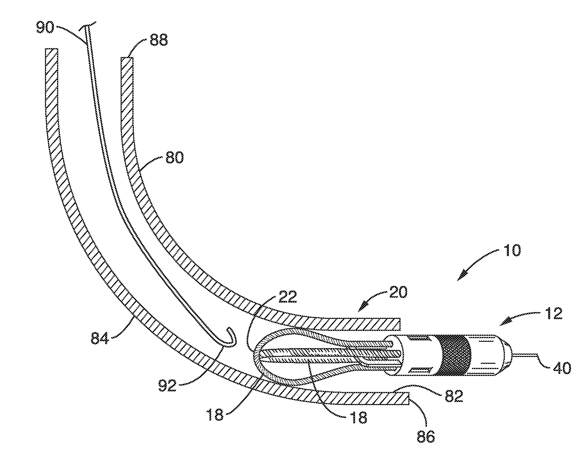
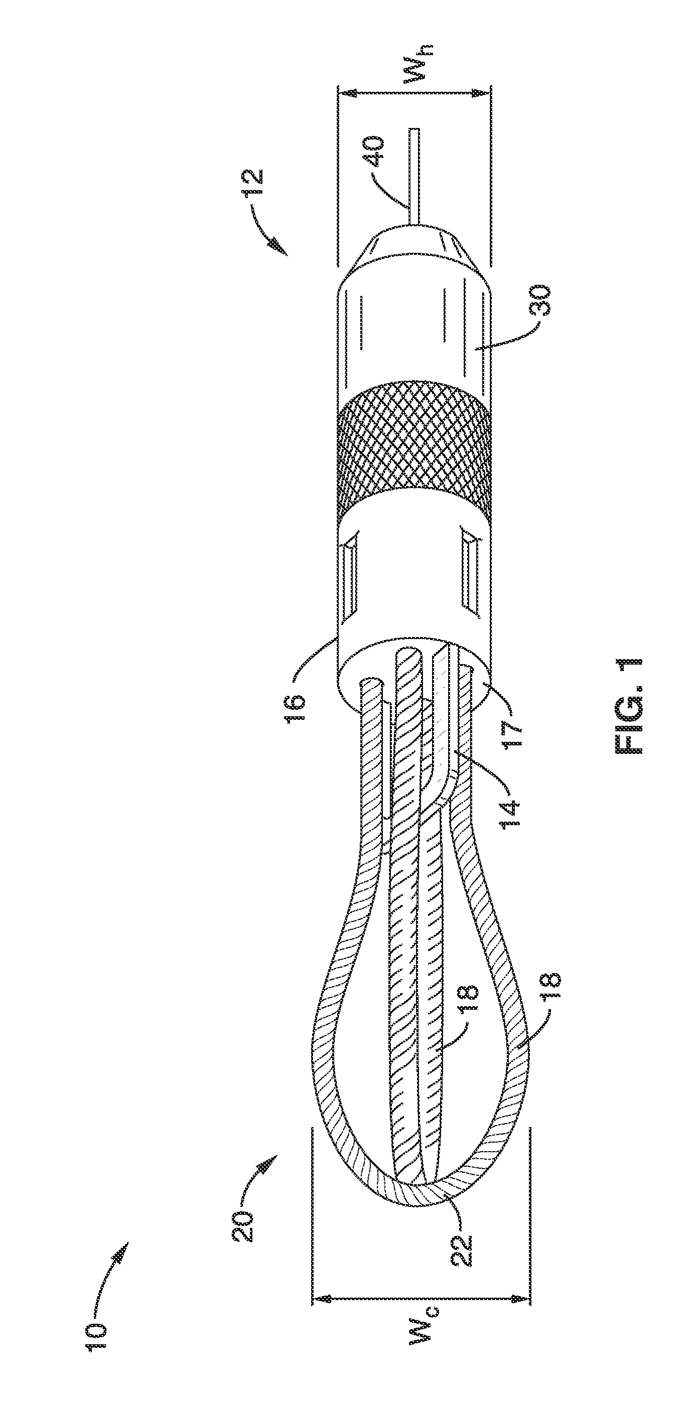
[0048]2. The leader of embodiment 1, further comprising: a second resilient elongate member having first and second ends; wherein the second resilient elongate member is bent to form a second resilient preformed loop, with the first and second ends attached to the leading end of the housing such that the first and second ends emanate longitudinally from the leading end of the housing; wherein the second preformed loop extends longitudinally and laterally from the leading end of the housing to form a second curved leading edge substantially orthogonal to the first leading edge, the second preformed loop having a width greater than the width of the housing; and wherein the leader is configured to be advanced in a lengthwise direction through the conduit such that the second preformed loop simultaneously contacts two substantially opposing points of the inner wall of the conduit.

embodiment 2

[0049]3. The leader of embodiment 2, wherein the first and second preformed loops have widths sized to be greater than the diameter of the inner wall of the conduit such that the first and second preformed loops are configured to resiliently deform to accommodate the shape of the inner wall while being inserted into the conduit.

[0050]4. The leader of embodiment 2, wherein the first and second preformed loops are configured to provide an anchor point to allow the leader to be pulled from an opposite direction within the conduit.

[0051]5. The leader of embodiment 1, further comprising: a coupling releasably attached to the trailing end of the housing; wherein the coupling comprises a slotted member; the slotted member having a slot-shaped thru-hole having a width sized to allow the tape to advance through the slot when the tape is in a non-deformed state; the thru-hole further sized to retain an end of the fish tape from advancing past the thru-hole when the end of the fish tape is tor...

embodiment 5

[0052]6. The leader of embodiment 5, wherein the coupling comprises: a base having an open end and a trailing end; wherein the open end comprises attachment means for releasably coupling the trailing end of the housing to the base; the trailing end of the base comprising an aperture for receiving the end of the fish tape, the aperture being in communication with the open end via a cavity; wherein the slotted member comprises a bead comprising the slot-shaped thru-hole; and wherein the aperture is sized to retain the bead from advancing out of the cavity past the aperture.


PUM

PropertyMeasurementUnit
timeaaaaaaaaaa
lengthaaaaaaaaaa
lengthaaaaaaaaaa

Abstract

A fish tape leader and coupling are disclosed wherein the coupling attaches to a fish tape using an adaptor that fits within the coupling and has a slot through which the fish tape can be inserted. Twisting the fish tape deforms the tape so that the tape cannot be pulled back through the adaptor and coupling.

Description

CROSS-REFERENCE TO RELATED APPLICATIONS[0001]This application claims priority from U.S. provisional application Ser. No. 61 / 388,862 filed on Oct. 1, 2010, herein incorporated by reference in its entirety.STATEMENT REGARDING FEDERALLY SPONSORED RESEARCH OR DEVELOPMENT[0002]Not ApplicableINCORPORATION-BY-REFERENCE OF MATERIAL SUBMITTED ON A COMPACT DISC[0003]Not ApplicableNOTICE OF MATERIAL SUBJECT TO COPYRIGHT PROTECTION[0004]A portion of the material in this patent document is subject to copyright protection under the copyright laws of the United States and of other countries. The owner of the copyright rights has no objection to the facsimile reproduction by anyone of the patent document or the patent disclosure, as it appears in the United States Patent and Trademark Office publicly available file or records, but otherwise reserves all copyright rights whatsoever. The copyright owner does not hereby waive any of its rights to have this patent document maintained in secrecy, includ...

Claims


Application Information

Patent Timeline
Patent Type & Authority Applications(United States)
IPC IPC(8): H02G1/08F16G11/00F16G11/12B23P11/00
CPCH02G1/081H02G1/083Y10T24/39Y10T29/49959Y10T24/3991
Inventor DAVIDSON, SCOTTNEVEROV, ALEKSEY
Owner DAVIDSON SCOTT
Learn More