
Method and apparatus for detecting state of charge of battery

a technology of state of charge and battery, which is applied in the direction of material analysis, instruments, transportation and packaging, etc., can solve the problems of inability to accurately detect the state of charge of the battery, and the inability to meet the requirements of the battery. achieve the effect of convenient soc measurement and fast and precise soc measuremen

Active Publication Date: 2012-03-22
LITE ON TECH CORP
View PDF0 Cites 26 Cited by
  • Summary
  • Abstract
  • Description
  • Claims
  • Application Information

AI Technical Summary

Benefits of technology

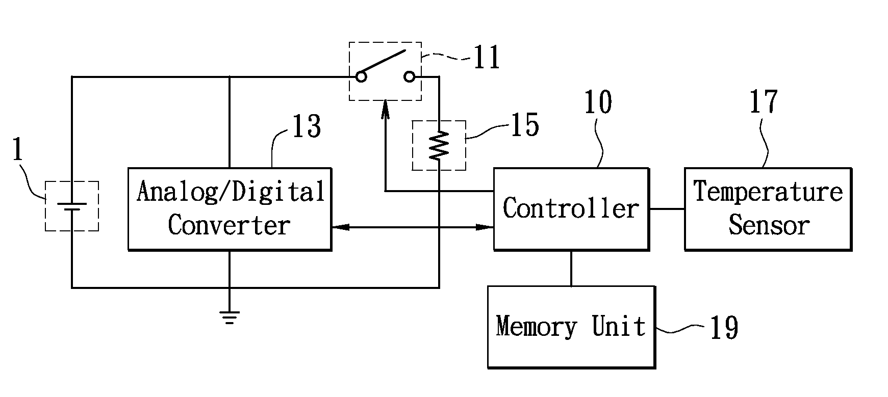
The present invention provides a method and apparatus for detecting the state of charge (SOC) of a battery. The technical effects of this invention include fast and precise measurements of battery SOC, with the required components directly installed on the battery management system, and the ability to measure the battery's SOC even when it is not stationary for a long period. The method uses a single frequency pulse to measure the battery's response curve, and calculates a simulated curve based on the parameters of the battery. This allows for a simple and accurate method of determining the battery's SOC, even in the presence of interferences and polarization effects.

Problems solved by technology

However, the conventional measuring methods are associated with their disadvantages.
Although the open circuit voltage measuring is relatively simpler, the measuring may take too much time in remaining the battery stationary to reach an equivalent state.
Also, the open-circuit voltage method may be not accurate for those batteries whose open-circuit voltage changes comparatively small with the SOC (e.g., a lithium iron phosphate battery).
This method consumes excessively long time on collecting relevant parameters and corresponding computations are complicated when the issue of the polarization of the battery is taken into consideration.
Meanwhile, the equipments implementing such measuring method are expensive and the entire measuring process needs to be accomplished offline, all of which can not fulfill the demands for general battery management systems.

Method used


Image

  • Method and apparatus for detecting state of charge of battery
  • Method and apparatus for detecting state of charge of battery
  • Method and apparatus for detecting state of charge of battery

Examples


Embodiment Construction

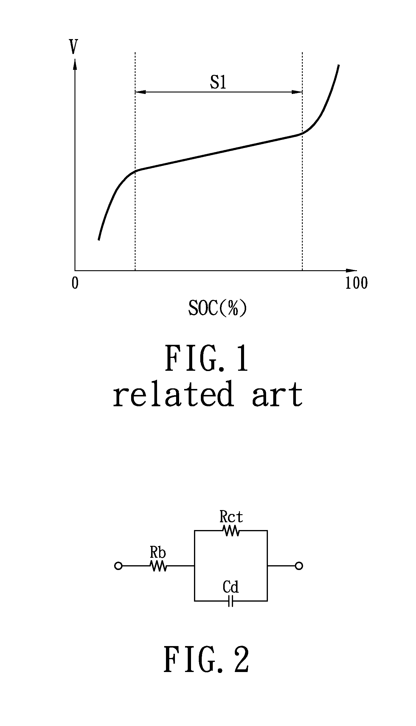
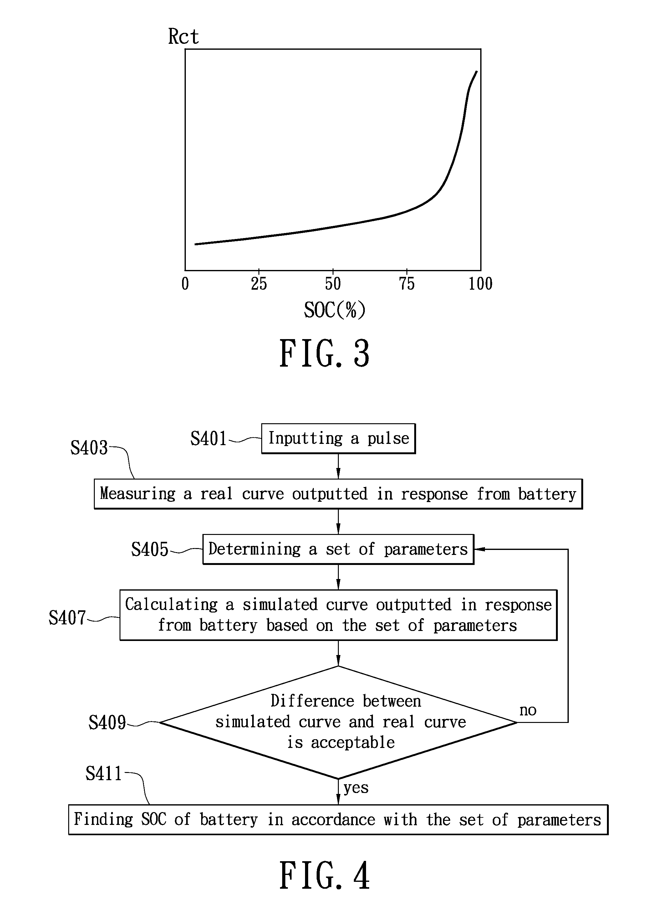
[0024]Before further explaining the present invention, please refer to FIG. 2 in which an equivalent circuit diagram of a general battery is shown. The general battery may at least include a bulk resistor (Rb), a charge transfer resistor (Rct) and an electric double layer capacitor (Cd). A relationship exists correspondingly between the charge transfer resistor and the SOC, as shown in FIG. 3, where the above-mentioned corresponding relationship in terms of a curve is illustrated. FIG. 3 shows that the different charge transfer resistors may correspond to different SOC values. Therefore, the SOC of battery can be effectively located through the curved corresponding relationship shown in FIG. 3 if the resistance of the charge transfer resistor in the battery could be determined.

[0025]The technical features applied in the present invention are characterized in inputting a pulse to a battery thereby measuring and receiving a set of parameters according to the equivalent circuit of the ...


PUM

PropertyMeasurementUnit
currentaaaaaaaaaa
state of chargeaaaaaaaaaa
thresholdaaaaaaaaaa

Abstract

A method for detecting a state of charge (SOC) of a battery is disclosed. The method includes inputting a pulse to the battery for receiving a response curve of the battery associated with the pulse inputted to the battery, determining a set of parameters for preparing a simulated curve, comparing a difference between the response curve and the simulated curve, determining whether the difference between the simulated curve and the response curve is less than a predetermined threshold before further utilizing the parameters to determine the SOC from a corresponding relationship.

Description

BACKGROUND OF THE INVENTION[0001]1. Field of the Invention[0002]The present invention relates to a detection method and apparatus; in particular, to a method and apparatus for detecting the state of charge (SOC) of a battery.[0003]2. Description of Related Art[0004]In order to ensure safe operations of a battery, over-charge or over-discharge should be prevented to protect the battery from irreversible change of electrochemical characteristic inside the battery which deteriorates the performance and lowers the lifespan of the battery. Therefore, in order to avoid over-charge or over-discharge, the processes of charging or discharging must be stopped before the battery reaches its upper limit of charging capacity or the lower limit of discharging capacity. Consequently, by measuring the state of charge (SOC) of the battery, the change of the electrochemical characteristic of the battery could be monitored during battery charge / discharge processes to ensure that the battery is being u...

Claims


Application Information

Patent Timeline
Patent Type & Authority Applications(United States)
IPC IPC(8): G01R31/36G01N27/416
CPCG01R31/3651G01R31/3637G01R31/388G01R31/367
Inventor HSU, YUEH-TENGYEH, CHIA-FU
Owner LITE ON TECH CORP
Learn More