
Vehicular lamp

Inactive Publication Date: 2012-03-22
KOITO MFG CO LTD
View PDF11 Cites 97 Cited by
  • Summary
  • Abstract
  • Description
  • Claims
  • Application Information

AI Technical Summary

Benefits of technology

[0012]In view of this fact, the present inventors considered that, if a translucent diffusion cover was provided in front of the light guide neighboring region (especially in front of the gap), the light would be diffused by the diffusion cover and the gap between the light guides would therefore become hard to see when the light source was unlit and on the other hand, when the light source

Problems solved by technology

However, a new problem arises that, since a gap occurs in the light guide neighboring region, in which the light guides are disposed adjacent to each other, the sense of continuity (unity) of the light guide is not provided in either of the case where the light source is lit and the case where the light source is unlit.

Method used


Image

  • Vehicular lamp
  • Vehicular lamp
  • Vehicular lamp

Examples


first embodiment

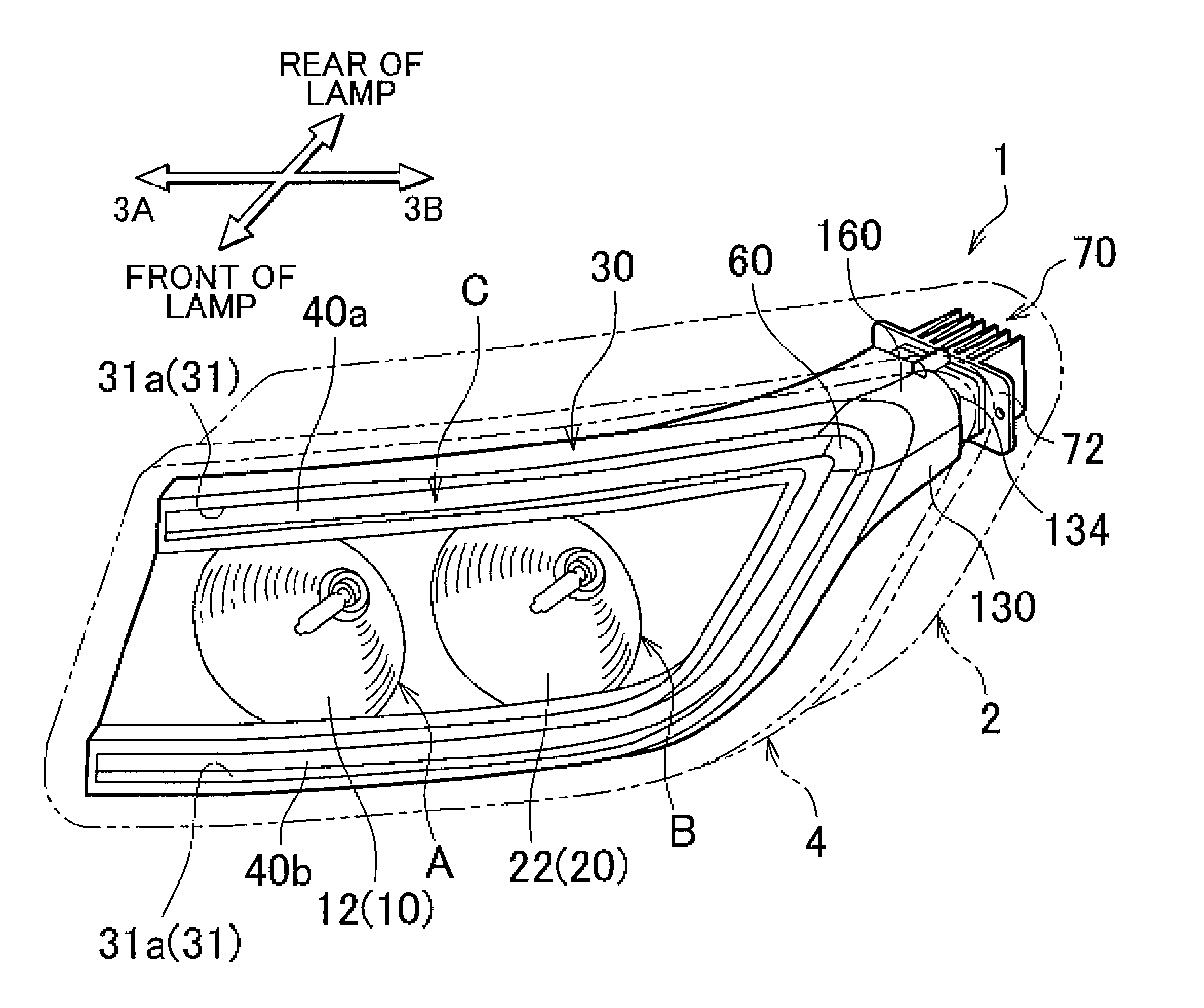
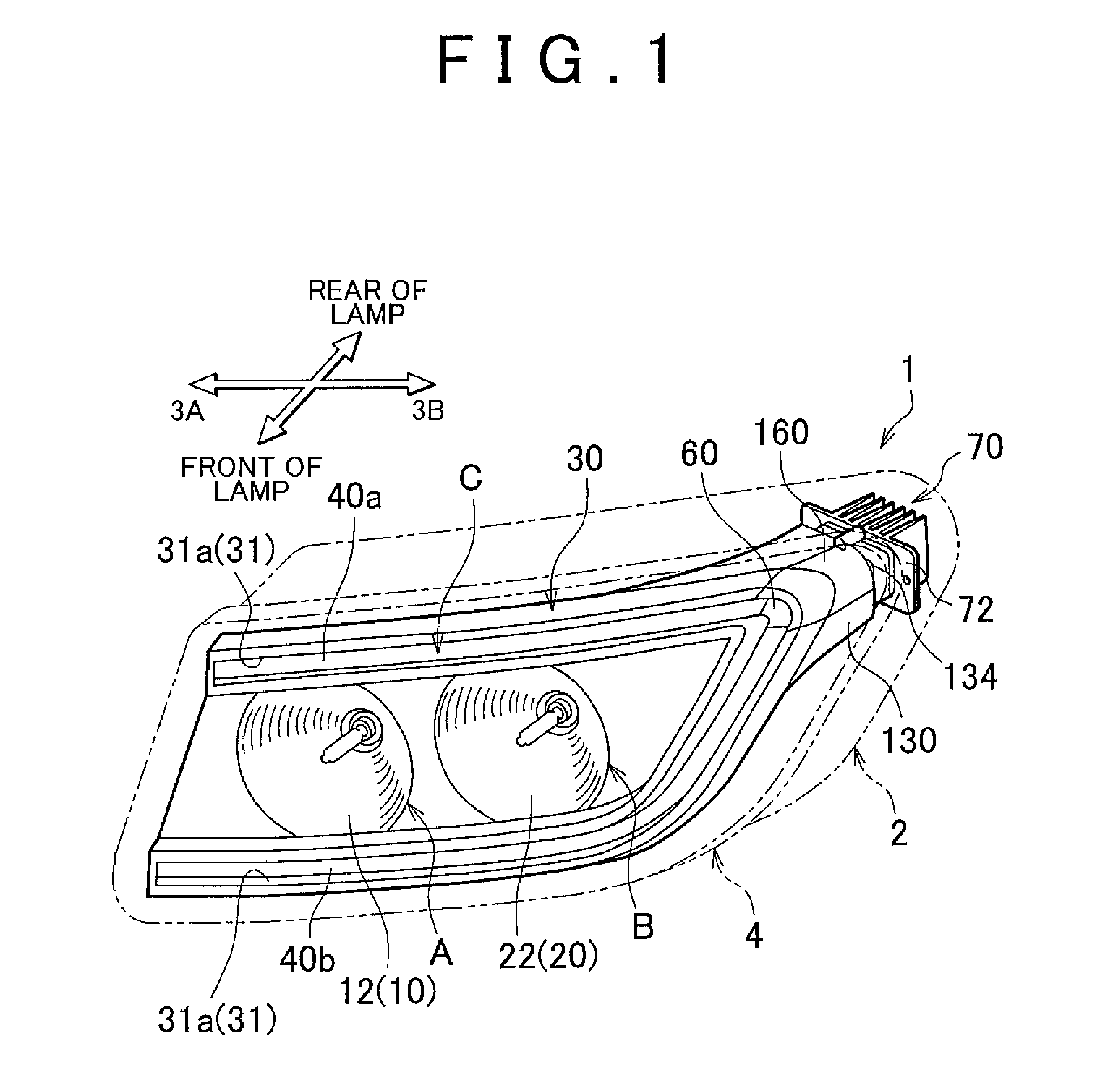
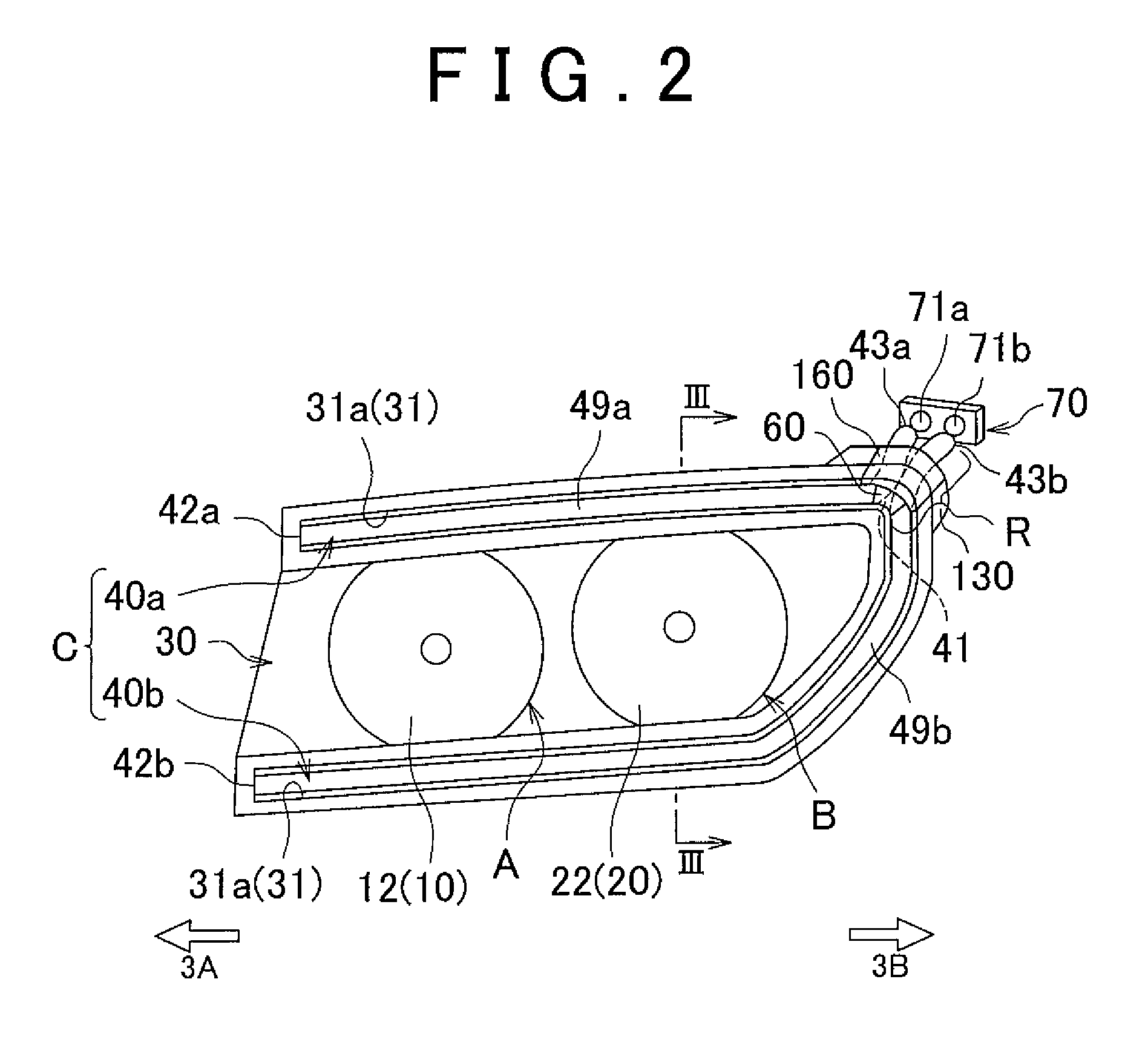
[0069]The light that leaks from (the end-branch portion regions 149a and 149b of) the light guide neighboring region R is reflected by the inner surface 82 of the sub-reflector 80 toward the front of the lamp and part of the reflected light is emitted through the curved cover 60A (the neighboring portion 60A1 of the light guide neighboring region R thereof), so that the amount of light emitted through the neighboring portion 60A1 that is close to the neighboring region R increases, which makes the entire curved cover 60A appear as if it emits light uniformly. At the same time, as in the case of the first embodiment, the light that leaks from the end-branch portion regions 149a and 149b and that is unwanted in view of the purpose of making the entire light guides (lamp C) appear as if the light guides emit light in the C shape that is inclined to rise toward the right and that conforms with the form (rounded shape) of the headlamp 1, is shielded by the light-shielding cover 160.

[0070...

third embodiment

[0074]FIG. 10 is a front view of a headlamp according to the present invention with the outer cover and the lamp body removed. In FIG. 10, LED assemblies 70A and 70B are simplified.

[0075]The third embodiment is similar to the second embodiment, except that the linear light guides 40a and 40b of the second embodiment are changed in shape into linear light guides 40A and 40B as described later, the curved cover 60A is changed in shape into a curved cover 60B in conformity with the light guides 40A and 40B, an LED assembly attachment portion 130B is provided also at a lower right position when viewed from the front, and a light-shielding cover 160B is provided also at the LED assembly attachment portion 130B.

[0076]The linear light guides 40A and 40B each have a generally L shape and the light guide 40A is extended from a light incidence end portion 43A connected to the LED assembly 70B and drawn into the LED assembly attachment portion 130B, and is attached to (the groove 31 of) the ex...

second embodiment

[0080]In addition, the curved cover 60B has a width substantially equal to that of two light guides so as to cover the front side of the light guide neighboring region R (parallel light-emitting portions 149A and 149B) and is disposed to extend in a shape similar to that of the

[0081]The light-shielding cover 160B is integrated so as to be flush with the surface 35 of the extension 30 by attaching the light-shielding cover 160B so as to conform with the form (rounded shape) of the extension 30 and close the lower right opening (not shown). In other words, the light-shielding covers 160 and 160B are shaped so as to cover the vicinities of the light incidence end portions 43B and 43A, respectively.

[0082]If the curved cover 60B is not provided, the light guide intersection portion 41B of the light guides 40A and 40B in the light guide neighboring region R can be seen through the outer cover 4 when the LEDs 71a and 71b are unlit, which impairs the appearance. In addition, when the LEDs 7...


PUM


Abstract

A linear light guide or light guides disposed in a lamp chamber have a light guide neighboring region, in which the portions close to light incidence end portions are close to each other, and a light-emitting portion or portions are disposed so as to be offset from a luminous region of a light source unit and to have portions that extend from the light guide neighboring region and separate from each other. A translucent diffusion cover that covers the light guide neighboring region is provided at least in front of the light guide neighboring region. Part of the light from the light guide neighboring region is diffused by the diffusion cover and then emitted through the diffusion cover, so that light emitted through the light-emitting portion and the diffusion cover is continuous, so that it appears as if the light guide that is continuous is emitting light.

Description

INCORPORATION BY REFERENCE[0001]The disclosure of Japanese Patent Application No. 2010-209270 filed on Sep. 17, 2010 including the specification, drawings and abstract is incorporated herein by reference in its entirety.BACKGROUND OF THE INVENTION[0002]1. Field of the Invention[0003]The present invention relates to a vehicular lamp, in which a linear light guide serving as a light-emitting object is accommodated in a lamp chamber defined by an outer cover and a lamp body and in particular to a vehicular lamp configured so that it appears as if the linear light guide is continuous at the point, at which portions of the linear light guide are adjacent to each other.[0004]2. Description of Related Art[0005]Examples of the vehicular lamp, such as a clearance lamp and a day time running lamp, for making drivers of the cars in the opposite lane and others recognize the host vehicle include a lamp, in which light source light is reflected by a reflector to distribute the light, and a lamp,...

Claims


Application Information

Patent Timeline
IPC IPC(8): F21V8/00
CPCB60Q1/0052F21S48/215F21S48/22F21S48/2237F21S48/328F21S48/2287F21S48/24F21S48/25F21S48/2268F21S41/24F21S43/14F21S43/20F21S43/237F21S43/245F21S43/247F21S43/40F21S43/50F21S45/48
Inventor NATSUME, KAZUNORIARAI, HAJIME
Owner KOITO MFG CO LTD
Learn More