
LED landing light arrangement for an aircraft

a technology for landing lights and aircraft, which is applied in the direction of portable electric lighting, rotocraft, light and heating equipment, etc. it can solve the problems of wasting relatively much light, unable to offer the pilot hid landing lights, and light fixtures that are not suited to enlarge and improve the pilot's illuminated field

Active Publication Date: 2012-03-22
GOODRICH LIGHTING SYST GMBH
View PDF6 Cites 11 Cited by
  • Summary
  • Abstract
  • Description
  • Claims
  • Application Information

AI Technical Summary

Benefits of technology

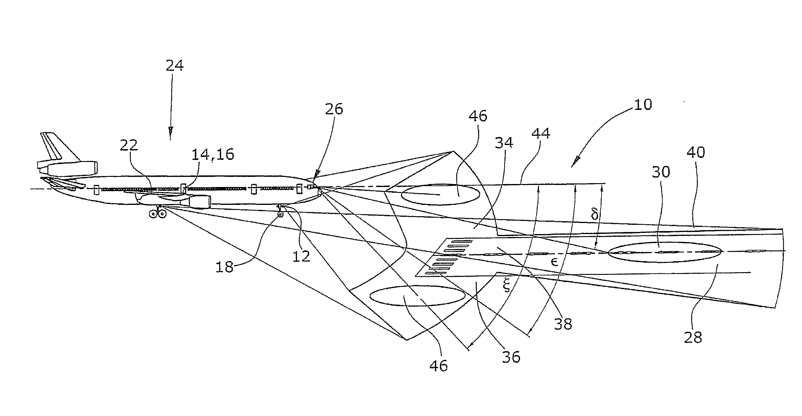
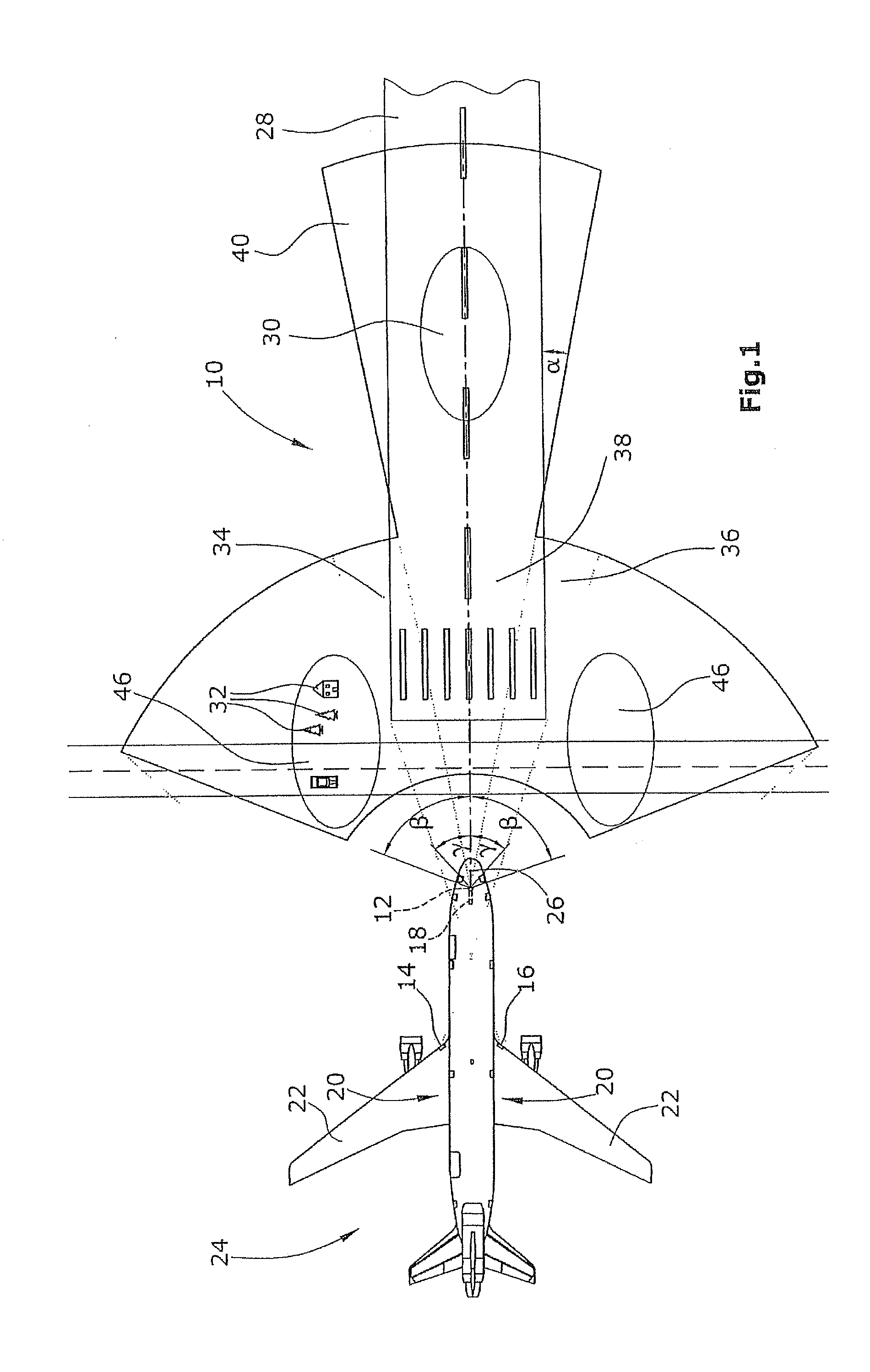
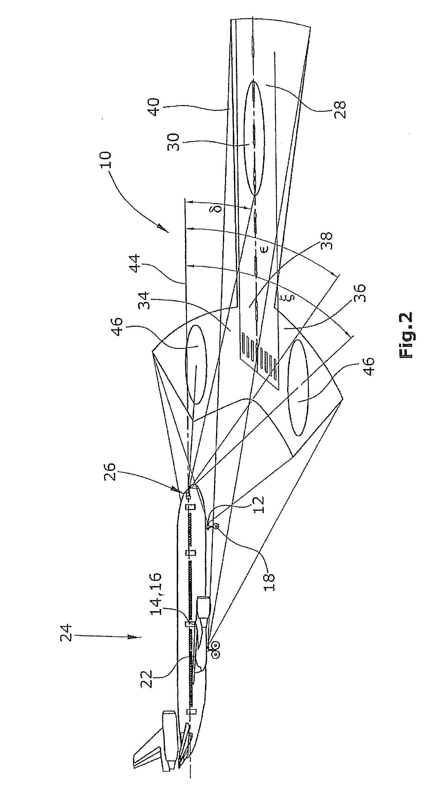
The invention is an LED landing light arrangement for aircraft that generates a Y-shaped light distribution in front of the aircraft during the landing approach. The light distribution has two curved lateral regions and a central region running from the lateral regions along the aircraft's central axis. The light distribution is symmetrically spread across the aircraft's lateral angles and within a certain distance from the aircraft. The orientation of the light distribution is downward by a certain angle and within a specific lateral-angle region. The technical effect of this LED landing light arrangement is to provide better visibility and improved safety for the pilot and other personnel during the landing approach.

Problems solved by technology

Thus, these lights are not suited to enlarge of improve the pilot's illuminated field of view during the landing approach.
In landing lights of the types currently in use, however, relatively much light will be wasted as stray light, which is caused by shading and insufficient intensity.
Further, HID landing lights cannot be used for offering the pilot an obliquely downward view of the ground.
The narrow light strips generate a “finger” effect with high differences in the illuminating light, which, due to the lateral-angle and elevation-angle variations of the aircraft during the landing approach, has the consequence that the illuminated areas will “dance” on the ground, so that no all-inclusive illumination of the landing strip will be possible.

Method used


Image

  • LED landing light arrangement for an aircraft
  • LED landing light arrangement for an aircraft
  • LED landing light arrangement for an aircraft

Examples


Embodiment Construction

[0019]The invention is based on the idea of using a dedicated, non-rotationally-symmetric light distribution which is particularly enhanced by the use of LEDs, wherein, with the aid of this light distribution, the pilot's field of view during landing approach can be used to a distinctly larger extent by improving its illumination. According to the invention, the light distribution has a spread shape resembling that of the letter Y, with the two arms of said Y-shape, diverging from the “shaft” of the Y, being arranged laterally of the cockpit of the aircraft and converging in front of the cockpit. LEDs and particularly LED clusters are well-suited for realizing the different orientations of light sources of a light device relative to each other, and thus allow for simple adjustment to the desired light distribution.

[0020]The light flux emitted by LED lights, when considered in relation to the size of the area to be illuminated, is relatively limited. For this reason, no portion of th...


PUM


Abstract

An LED landing light arrangement for an aircraft comprises a plurality of LED light sources (12,14,16) for arrangement on an aircraft (24), primarily on the wing roots (20), on the front edges of the wings (22) and / or on the landing gears (18). The LED light sources (12,14,16) are operative to generate, relative to the central axis of the aircraft (24), a light distribution (10) ahead of the aircraft (24) that is spread substantially in a Y-shaped configuration in an obliquely downward direction. The light distribution (10) comprises two converging lateral regions (34,36) arranged laterally ahead of the aircraft (24), and a central region (40) running from said converging lateral regions (34,36) along an extension of said central axis and oriented in a direction away from the aircraft (24).

Description

RELATED CROSS-REFERENCING[0001]The present invention claims the priority of European Patent Application EP 10 178 284.4 filed on Sep. 22, 2010, the disclosure of which is incorporated herein by reference.BACKGROUND OF THE INVENTION[0002]1. Field of the Invention[0003]The invention relates to an LED landing light arrangement for an aircraft with improved illumination of the regions laterally of the cockpit and in front of the cockpit during the aircraft's landing approach, touchdown and rolling movement on the landing strip, on the taxiway and on the field in front of the terminal. The LED landing light arrangement of the invention improves the safety and the comfort for the pilot of the aircraft as well as the visibility of the aircraft to persons external of the aircraft.[0004]2. Description of the Prior Art[0005]Aircraft presently in service are provided with landing lights which are used during the landing approach of the aircraft and are arranged in the wing roots and on the fro...

Claims


Application Information

Patent Timeline
Patent Type & Authority Applications(United States)
IPC IPC(8): B64D47/04
CPCB64D47/04B64C2027/8236B64D2203/00
Inventor WILLEKE, BENJAMINBEIER, ENRICOWERNICKE, ALEXANDERHESSLING, ANDRE
Owner GOODRICH LIGHTING SYST GMBH
Learn More