
Beverage dispenser

Inactive Publication Date: 2012-03-08
COSMO LIFE
View PDF12 Cites 12 Cited by
  • Summary
  • Abstract
  • Description
  • Claims
  • Application Information

AI Technical Summary

Benefits of technology

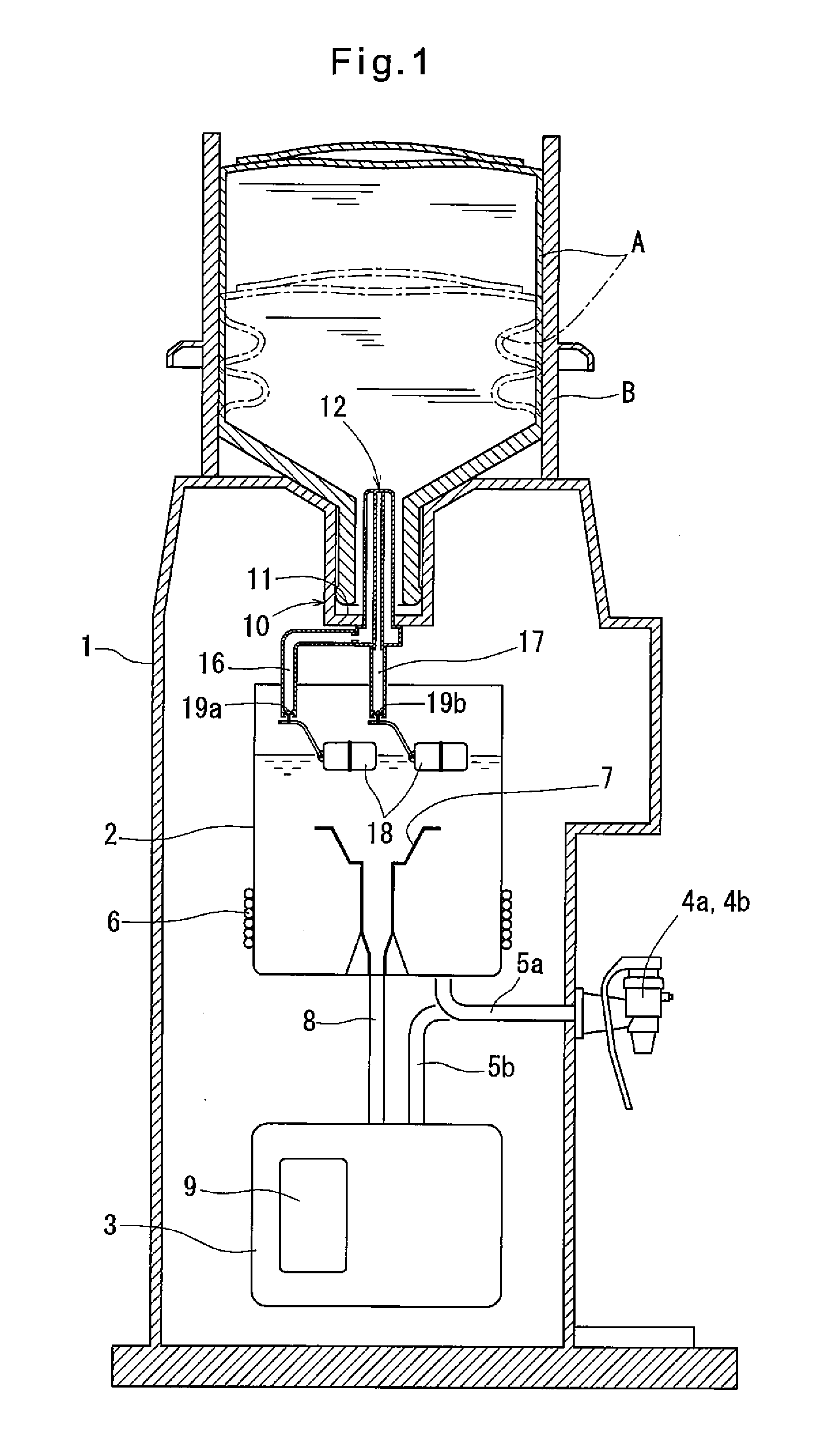
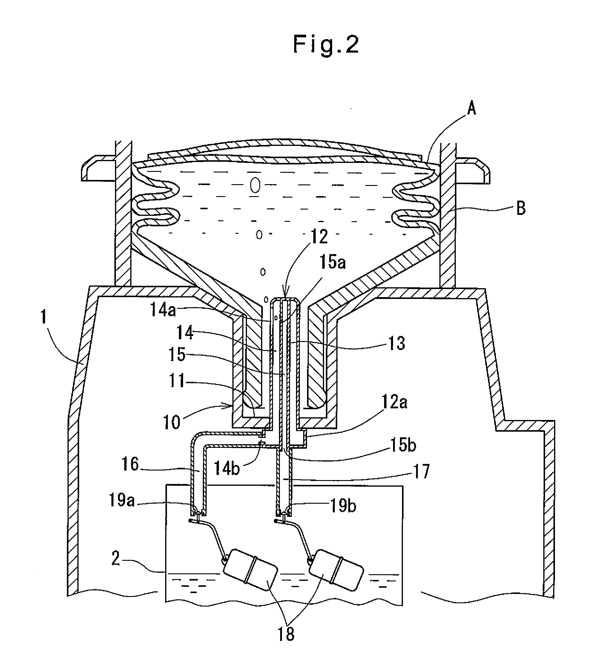
[0009]With the arrangement wherein the interior of the water passage tube has a cross-section which is partitioned into a water passage through which the water passage hole communicates with the first opening, and an air passage communicating with a small air passage hole which opens to the water passage or the interior of the outlet port and having a second opening at a lower end portion of the air passage, and wherein the beverage dispenser further comprises an air passage pipe connected to the second opening and hanging into the tank, and a second on-off valve provided at a free end of the air passage pipe and configured to open when the water level in the tank lowers, when drinking water in the container runs low and stops dropping and as a result, the water level in the tank remains low, air in the tank is introduced into the container through the second on-off valve, which is now open, the air passage pipe, the air passage, and the small air passage hole. This eliminates the negative pressure in the container, thus allowing driving water remaining in the container to be completely dropped into the tank. Thus, it is possible to automatically and spontaneously use up drinking water in the container. Since air introduced into the container from the tank is cleaner than outer air, the interior of the container is less likely to be contaminated.
[0010]It is not clearly known why air in the tank flows into the air passage through the air passage pipe when drinking water in the container runs low and stops dropping into the tank and as a result, the water level in the tank remains low. But this is presumably because while drinking water in the container runs low and stops dropping and the pressure of the water in the container is substantially equal to the atmospheric pressure, the pressure in the air passage, which communicates with the interior of the container through the small air passage hole, tends to fluctuate, producing a difference between the pressure in container and the pressure in the air passage, and due to this pressure difference, i.e. a slight difference between the pressure in the air passage and the atmospheric pressure, drinking water in the water passage drops and thus air in the tank flows into the air passage through the air passage pipe. Air introduced into the air passage then flows into the container and rises through the water in the container in the form of air bubbles, thus eliminating the negative pressure in the container. When the water level in the tank decreases and the on-off valve of the air passage pipe opens while enough drinking water is stored in the container, the air passage is always completely filled with water and the amount of water that drops from the air passage pipe is always identical to the amount of water supplied into the air passage through the small air passage hole. Thus, no air is admitted into the air passage. The on-off valve of the air passage pipe is necessary because without this valve, even while there is enough water in the tank, drinking water would drop little by little into the tank from the water passage pipe.
[0013]The air passage pipe is preferably a straight pipe extending vertically from the second opening into the tank so that air introduced into the air passage pipe can smoothly flow into the air passage.
[0015]With the beverage dispenser according to the present invention, because the interior of the water passage tube has a cross-section which is partitioned into a water passage through which the water passage hole communicates with the first opening, and an air passage communicating with a small air passage hole which opens to the water passage or the interior of the outlet port and having a second opening at a lower end portion of the air passage, and the beverage dispenser further comprises an air passage pipe connected to the second opening and hanging into the tank, and a second on-off valve provided at a free end of the air passage pipe and configured to open when the water level in the tank lowers, when drinking water in the container runs low and stops dropping and as a result, the water level in the tank remains low, air in the tank is introduced into the container through the second on-off valve, which is now open, the air passage pipe, the air passage, and the small air passage hole. This eliminates the negative pressure in the container, thus allowing driving water remaining in the container to be completely dropped into the tank. Thus, it is possible to automatically and spontaneously use up drinking water in the container. Since air introduced into the container from the tank is cleaner than outer air, the interior of the container is less likely to be contaminated.
[0015]With the beverage dispenser according to the present invention, because the interior of the water passage tube has a cross-section which is partitioned into a water passage through which the water passage hole communicates with the first opening, and an air passage communicating with a small air passage hole which opens to the water passage or the interior of the outlet port and having a second opening at a lower end portion of the air passage, and the beverage dispenser further comprises an air passage pipe connected to the second opening and hanging into the tank, and a second on-off valve provided at a free end of the air passage pipe and configured to open when the water level in the tank lowers, when drinking water in the container runs low and stops dropping and as a result, the water level in the tank remains low, air in the tank is introduced into the container through the second on-off valve, which is now open, the air passage pipe, the air passage, and the small air passage hole. This eliminates the negative pressure in the container, thus allowing driving water remaining in the container to be completely dropped into the tank. Thus, it is possible to automatically and spontaneously use up drinking water in the container. Since air introduced into the container from the tank is cleaner than outer air, the interior of the container is less likely to be contaminated.

Problems solved by technology

This generates a negative pressure in the container, making it impossible to drop the remaining drinking water in the container into the tank.
Thus, it is impossible to use up drinking water in the container, at least not automatically.
In order to transfer such water remaining in the container into the tank, it is necessary to lift the raw water container until its outlet port separates from the container connecting portion, and incline the container to admit air into the container, thereby eliminating the negative pressure in the container. has to be the drinking water But since the raw water container is located at a high level, it is difficult to lift the container in a stable manner.
Also, drinking water may spill around the container connecting portion.

Method used


Image

  • Beverage dispenser
  • Beverage dispenser
  • Beverage dispenser

Examples


first embodiment

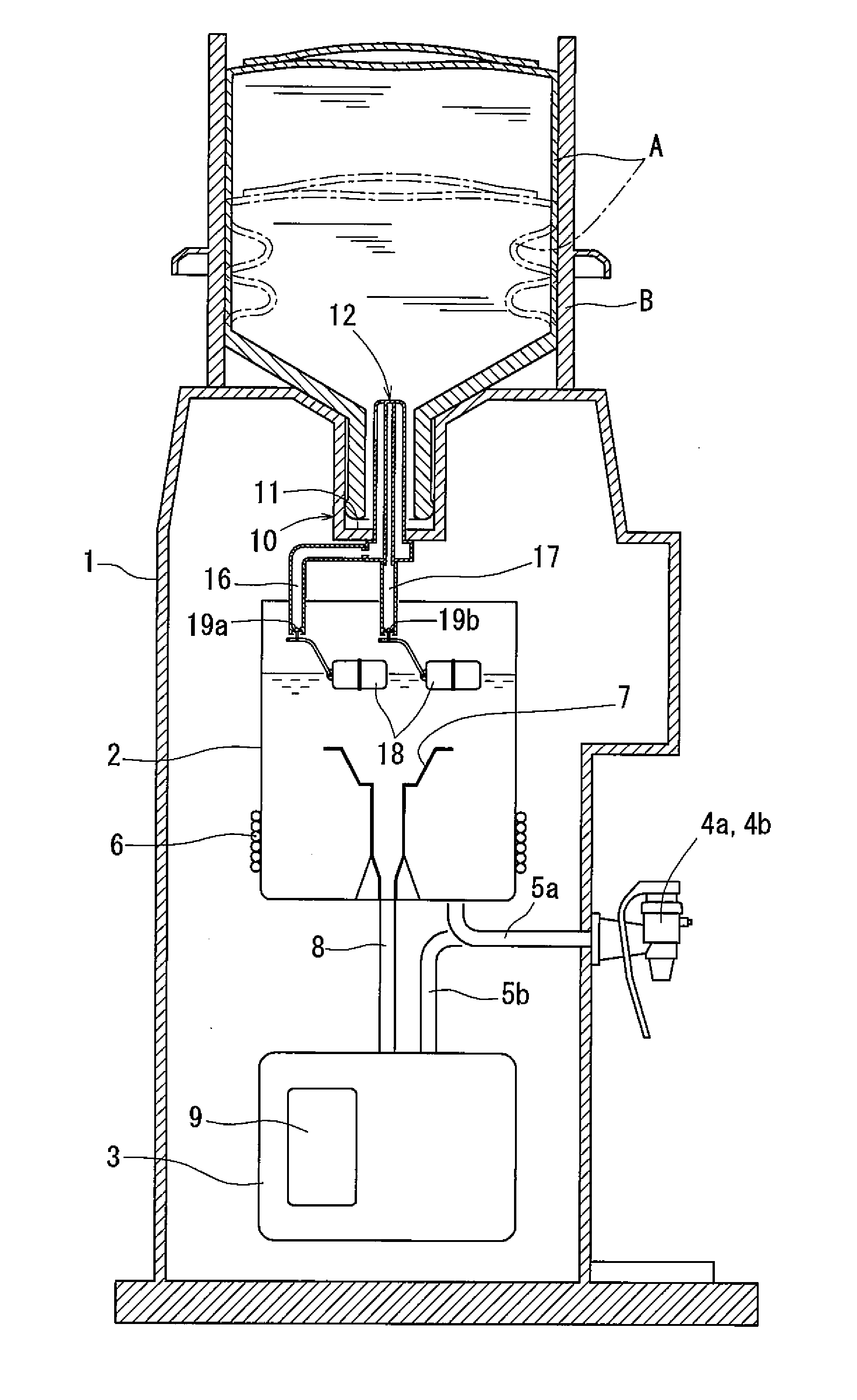
[0022]Now embodiments of the present invention are described with reference to the drawings. FIGS. 1 to 3 show the beverage dispenser of the first embodiment, which includes, as shown in FIG. 1, a container connecting portion 10 to which an outlet port of a raw water container A, which is filled with drinking water, is connected with the container A positioned such that its outlet port faces down. The container A is made of a soft material so that its side wall has flexibility. Under the container connecting portion 10, the beverage dispenser includes a low-temperature tank 2 and a high-temperature tank 3. The dispenser further includes a casing 1 and a cold water outlet valve 4a and a hot water outlet valve 4b provided at the front wall of the casing 1 and connected to the bottom of the low-temperature tank 2 and the ceiling of the high-temperature tank 3 through outlet pipes 5a and 5b, respectively. The raw water container A, which is made of a soft material, has its outer periphe...

second embodiment

[0031]FIG. 6 shows a modification of the second embodiment, in which the opening 14b of the water passage 14 and the opening 15b of the air passage 15 are both formed in the bottom of the base portion 12a of the water passage tube 12 in juxtaposition with each other. The water passage pipe 16 and the air passage pipe 17 extend vertically from the respective openings 14b and 15b in a straight line into the tank 2. The on-off valves 19a and 19b provided at the respective free ends of the water passage pipe 16 and air passage pipe 17, which are located close to each other, are opened and closed by a single float 18.

[0032]The beverage dispenser of either of the above embodiments has the low-temperature tank and the high-temperature tank, and is used to dispense water as a beverage. But the beverage dispenser may not include one of the tanks, and the beverage to be dispensed is not limited to water.


PUM


Abstract

A beverage dispenser is proposed which includes a soft raw water container and which makes it possible to spontaneously use up drinking water in the container. A water passage tube (12) of a container connecting portion (10) includes a tubular partitioning wall (13) dividing the interior of the water passage tube (12) into a water passage (14) communicating with a water passage hole (14a), and an air passage (15) communicating with the water passage (14) through a small air passage hole (15a). A water passage pipe (16) is connected to the water passage (14). The water passage tube (12) has a base portion (12a) formed with an opening (15b) communicating with the air passage (15). An air passage pipe (17) is connected to the opening (15b) and hangs vertically downwardly into a low-temperature tank (2). An on-off valve (19b) is provided at the free end of the air passage pipe (17) which is adapted to open when the water level in the low-temperature tank (2) lowers. With this arrangement, when drinking water in the raw water container (A) runs low and the water level in the low-temperature tank (2) remains low, air in the low-temperature tank (2) is introduced into the raw water container (A) through the on-off valve (19b), which is now open, the air passage pipe (17), the air passage (15) and the small air passage hole (15a). This eliminates a negative pressure in the raw water container (A), thereby allowing water remaining in the container to be dropped into the tank.

Description

TECHNICAL FIELD[0001]The present invention relates to a beverage dispenser for dispensing drinking water transferred from a raw water container into a tank through an outlet valve.BACKGROUND ART[0002]There is known a beverage dispenser comprising a raw water container for holding drinking water therein, a container connecting portion to which the outlet port of the raw water container can be connected with the outlet port facing downward, a tank provided under the connecting portion for holding drinking water dropped from the raw water container, and an outlet valve through which drinking water in the tank can be dispensed. In some of such beverage dispensers, a raw water container is used which is made of a soft material so that its side wall has flexibility (see e.g. Patent document 1).[0003]Such a raw water container can be collapsed during transportation, so that it can be transported efficiently. During use, as drinking water in the container drops, the container is gradually c...

Claims


Application Information

Patent Timeline
IPC IPC(8): B67D1/00B67D7/72B67D3/00B67C9/00
CPCB67D3/0009B67D3/0038B67D3/0032B67D3/0022Y10T137/3127B67D3/00F16K31/18
Inventor SHIOTANI, NANASHIOTANI, MASARU
Owner COSMO LIFE
Learn More