
Apparatus for determining a spatial output multi-channel audio signal

a multi-channel audio signal and spatial output technology, applied in electrical apparatus, stereophonic systems, stereophonic arrangments, etc., can solve the problems of unsatisfactory perceptual quality, high computational complexity, suitable decorrelation filters, etc., to achieve moderate computational cost, superior perceptual quality of rendered sound, and high perceptual quality

Active Publication Date: 2012-03-01
FRAUNHOFER GESELLSCHAFT ZUR FOERDERUNG DER ANGEWANDTEN FORSCHUNG EV
View PDF1 Cites 4 Cited by
  • Summary
  • Abstract
  • Description
  • Claims
  • Application Information

AI Technical Summary

Benefits of technology

This approach provides superior perceptual quality for critical audio materials like applause and ambience, reducing temporal smearing and computational complexity, while maintaining ambience stability and transient event clarity.

Problems solved by technology

For certain classes of signals as e.g. noise-like signals as for instance applause-like signals, conventional methods and systems suffer from either unsatisfactory perceptual quality or, if an object-orientated approach is used, high computational complexity due to the number of auditory events to be modeled or processed.
On the other hand, suitable decorrelation filters as, for example, all-pass filters, degrade a reproduction of quality of transient events, like a single handclap by introducing temporal smearing effects such as pre- and post-echoes and filter ringing.
A system utilizing the temporal permutation method, for example, will exhibit perceivable degradation of the output sound due to a certain repetitive quality in the output audio signal.
Furthermore, to avoid increased applause density, some original channels have to be dropped in the up-mix and, thus, some important auditory event might be missed in the resulting up-mix.
In object-orientated systems, typically such sound events are spatialized as a large group of point-like sources, which leads to a computationally complex implementation.

Method used


Image

  • Apparatus for determining a spatial output multi-channel audio signal
  • Apparatus for determining a spatial output multi-channel audio signal
  • Apparatus for determining a spatial output multi-channel audio signal

Examples


Embodiment Construction

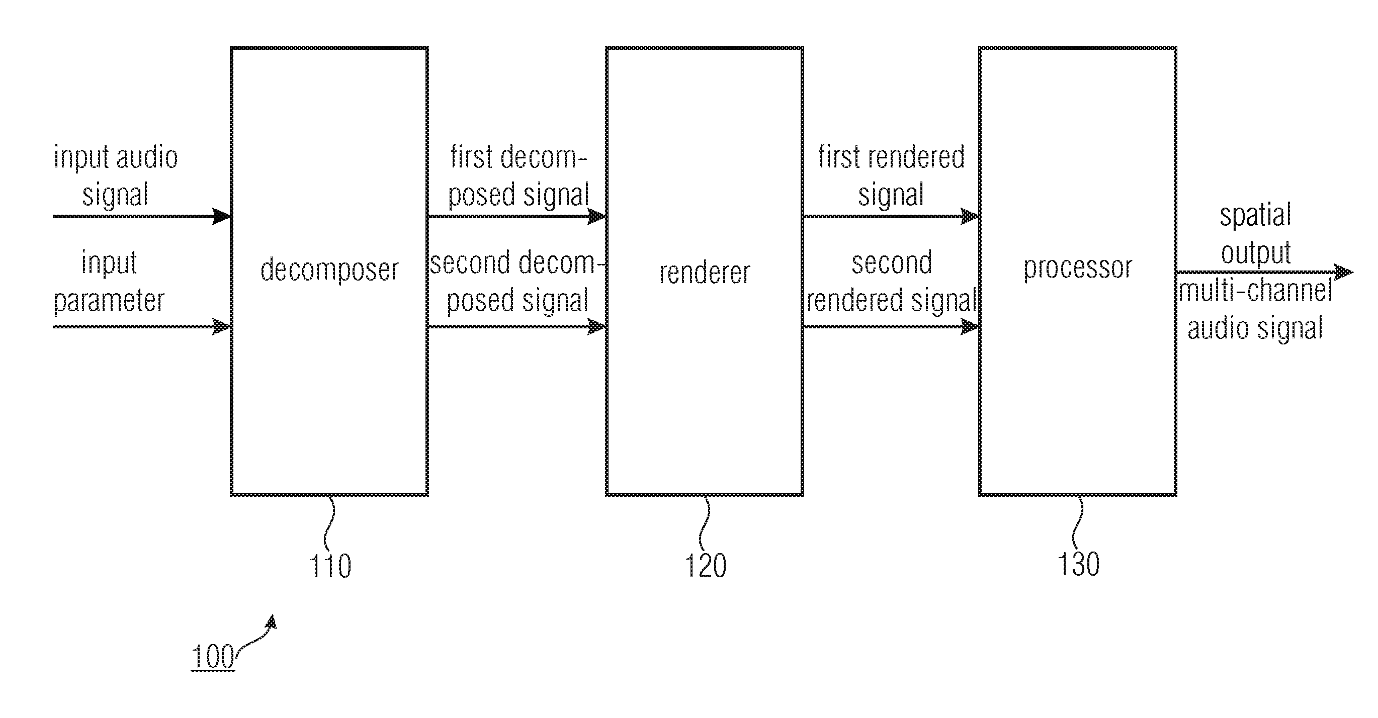
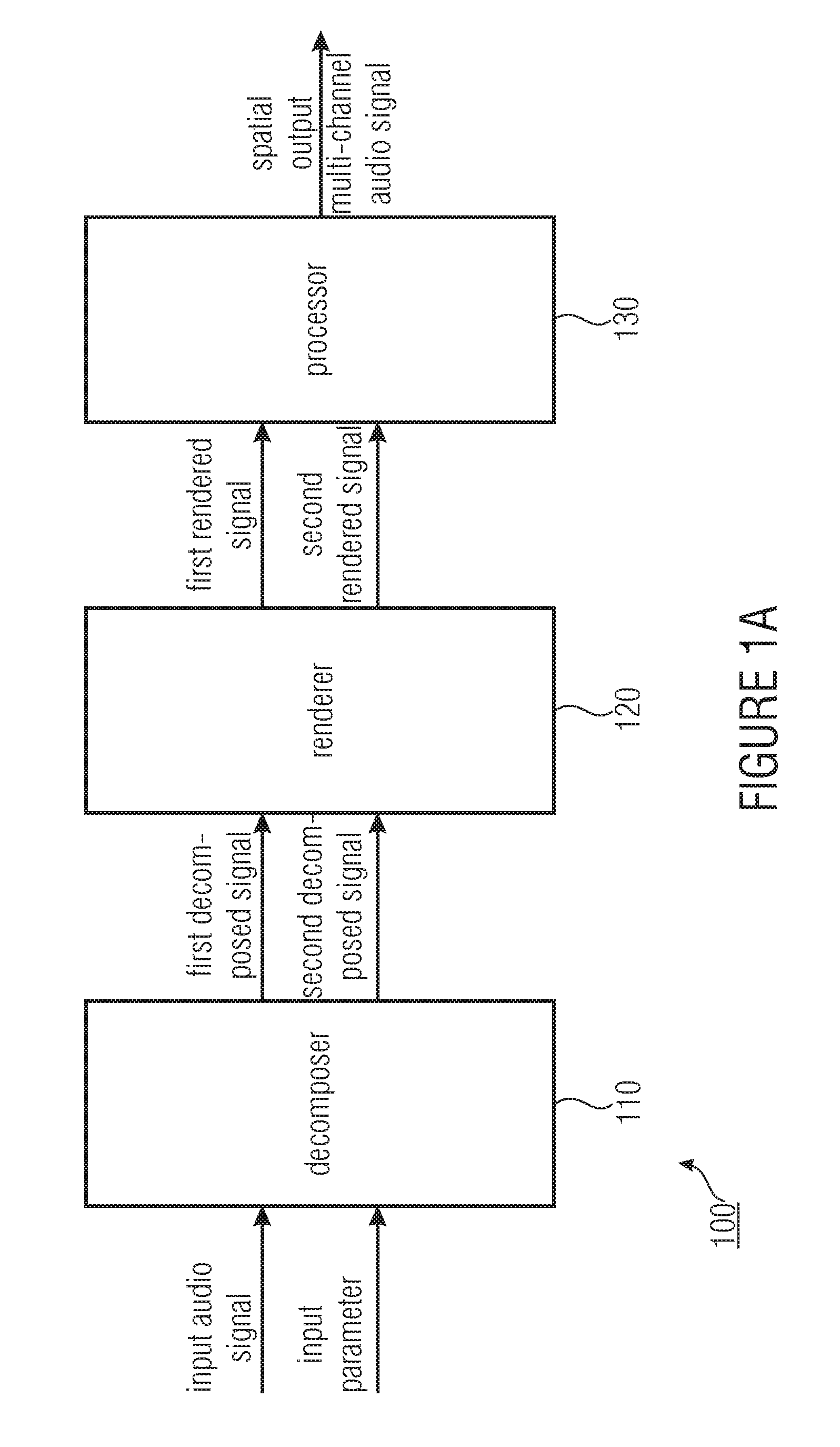
[0036]FIG. 1 shows an embodiment of an apparatus 100 for determining a spatial output multi-channel audio signal based on an input audio signal. In some embodiments the apparatus can be adapted for further basing the spatial output multi-channel audio signal on an input parameter. The input parameter may be generated locally or provided with the input audio signal, for example, as side information.

[0037]In the embodiment depicted in FIG. 1, the apparatus 100 comprises a decomposer 110 for decomposing the input audio signal to obtain a first decomposed signal having a first semantic property and a second decomposed signal having a second semantic property being different from the first semantic property.

[0038]The apparatus 100 further comprises a renderer 120 for rendering the first decomposed signal using a first rendering characteristic to obtain a first rendered signal having the first semantic property and for rendering the second decomposed signal using a second rendering charac...


PUM


Abstract

An apparatus for determining a spatial output multi-channel audio signal based on an input audio signal and an input parameter. The apparatus includes a decomposer for decomposing the input audio signal based on the input parameter to obtain a first decomposed signal and a second decomposed signal different from each other. Furthermore, the apparatus includes a renderer for rendering the first decomposed signal to obtain a first rendered signal having a first semantic property and for rendering the second decomposed signal to obtain a second rendered signal having a second semantic property being different from the first semantic property. The apparatus comprises a processor for processing the first rendered signal and the second rendered signal to obtain the spatial output multi-channel audio signal.

Description

CROSS-REFERENCE TO RELATED APPLICATIONS[0001]This application is a divisional of U.S. patent application Ser. No. 13 / 025,999, filed Feb. 11, 2011, which is a continuation of International Patent Application No. PCT / EP2009 / 005828 filed Aug. 11, 2009, and claims priority to U.S. Application No. 61 / 088,505, filed Aug. 13, 2008, and additionally claims priority from European Application No. EP 08 018 793.3, filed Oct. 28, 2008, all of which are incorporated herein by reference in their entirety.[0002]The present invention is in the field of audio processing, especially processing of spatial audio properties.BACKGROUND OF THE INVENTION[0003]Audio processing and / or coding has advanced in many ways. More and more demand is generated for spatial audio applications. In many applications audio signal processing is utilized to decorrelate or render signals. Such applications may, for example, carry out mono-to-stereo up-mix, mono / stereo to multi-channel up-mix, artificial reverberation, stereo...

Claims


Application Information

Patent Timeline
Patent Type & Authority Applications(United States)
IPC IPC(8): H04R5/00
CPCH04S7/30H04S2420/03H04S2400/11H04S7/00H04S3/00
Inventor DISCH, SASCHAPULKKI, VILLELAITINEN, MIKKO-VILLEERKUT, CUMHUR
Owner FRAUNHOFER GESELLSCHAFT ZUR FOERDERUNG DER ANGEWANDTEN FORSCHUNG EV
Learn More