
Auxiliary apparatus for better vacuuming effect

Active Publication Date: 2012-03-01
IND TECH RES INST
View PDF0 Cites 4 Cited by
  • Summary
  • Abstract
  • Description
  • Claims
  • Application Information

AI Technical Summary

Benefits of technology

[0005]The object of the present disclosure is to provide an auxiliary apparatus for vacuum cleaners, that not only is featured by its configuration of an independent second frame embedded with filters and an energy harvester in a manner that the filters in the second frame can prevent the energy harvester from being contaminated and thus clogged by dirt and dust while the energy harvester is operating for converting wind energy into electricity, but also is featured with its modularized design that the auxiliary apparatus can be easily detached from a vacuum cleaner as required.
[0006]To achieve the above object, the present disclosure provides an auxiliary apparatus for better vacuum cleaning effect, comprising:

Problems solved by technology

However, in a situation when a common household vacuum cleaner is used to clean certain areas that are lack of lighting, such as the area under a bed or sofa, users usually will find that it is difficult to proceed with the cleaning work in such dark environment since the accessories of the convenitonal household vacuum cleaner are not fitted with light sources designed for facilitating the cleaning work in poor lighting.
Nevertheless, although the applying of the airflow directly from the vacuum cleaner head upon the impeller or electric generator can be implemented directly and easily, the airflow directly from the vacuum cleaner head usually is saturated with dust and dirt, or even hairs and fibers that may easily cause the rotary elements in the impeller or electric generator to clog.
In addition, the wind power harvesters, such as the impellers and electric generators that are used in the aforementioned disclosures, are all being fixedly secured inside the vacuum cleaners, so that they can not be detached easily for maintenance.

Method used


Image

  • Auxiliary apparatus for better vacuuming effect
  • Auxiliary apparatus for better vacuuming effect
  • Auxiliary apparatus for better vacuuming effect

Examples


Embodiment Construction

[0017]For your esteemed members of reviewing committee to further understand and recognize the fulfilled functions and structural characteristics of the disclosure, several exemplary embodiments cooperating with detailed description are presented as the follows.

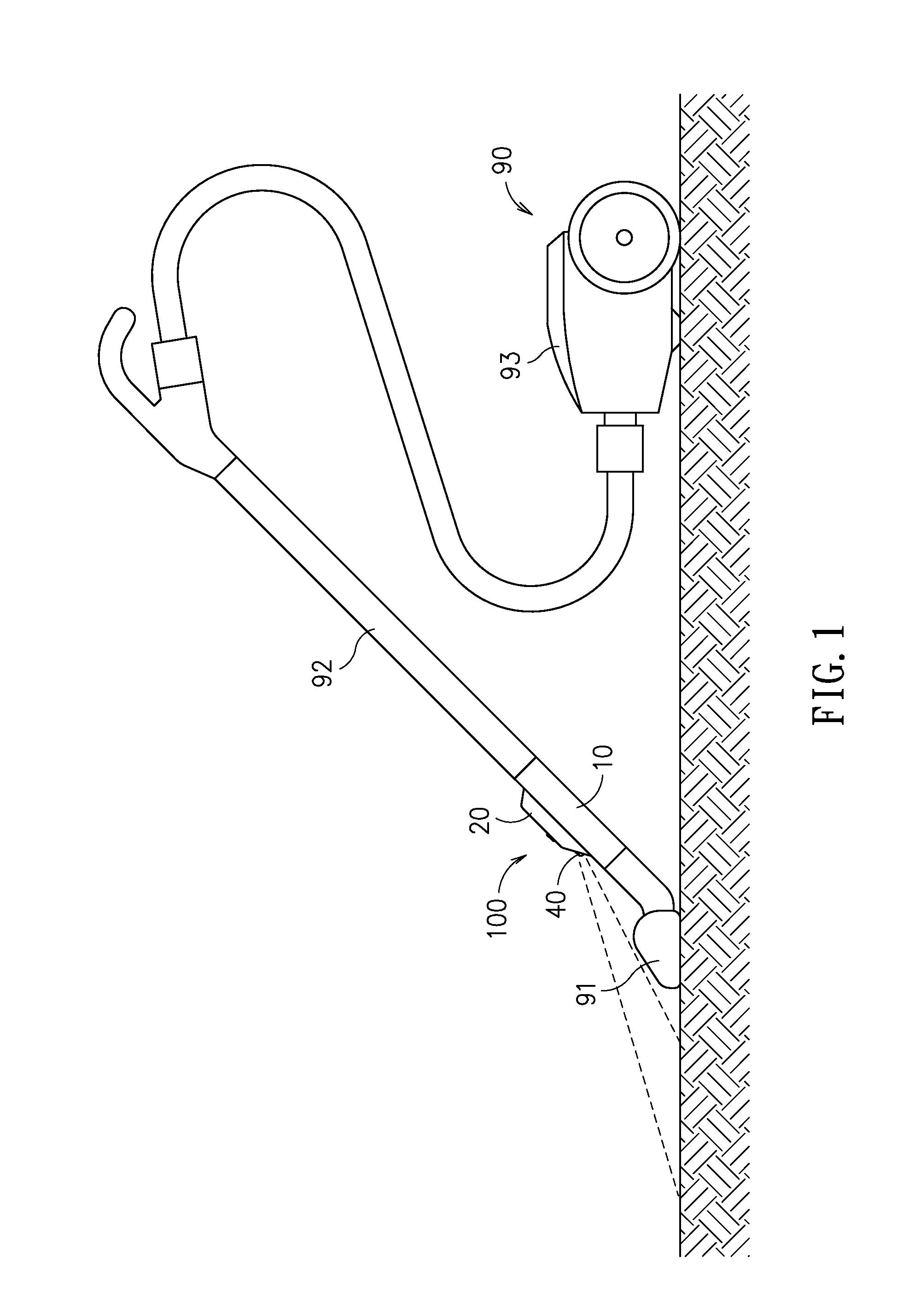
[0018]Please refer to FIG. 1, which is a schematic diagram showing an auxiliary apparatus of the present disclosure as it is fitted to a vacuum cleaner. As shown in FIG. 1, an auxiliary apparatus of the present disclosed can be assembled to a vacuum cleaner 90 at a position between the vacuum head 91 and its dust collecting tube 92, or can be sandwiched between and connected respectively to two dust collecting tubes of the vacuum cleaner 90, as shown in FIG. 7. When the vacuum cleaner 90 is activated, the motor received inside the mainframe 93 of the vacuum cleaner 90 is powered to operate at high speed and thus create a partial vacuum inside the main frame 93 to be used for inducing an airflow to suck up dust and dirt from i...


PUM


Abstract

An auxiliary apparatus for better vacuum cleaning effect, comprising: a first frame, formed with a first entrance and a first exit connected to the first entrance by a channel; a second frame, formed with a second entrance and a second exit, both arranged at positions between the first entrance and the first exit while being connected to the channel; and an energy harvester, wherein an airflow entering the first frame through the first entrance is split into a first airflow and a second airflow while enabling the first airflow to flow toward the first exit and the second airflow to flow into the second frame through the second entrance where it is guided toward the energy harvester for driving the same, and then the second airflow is guided to flow out of the second exit and enters the first frame for merging with the first airflow.

Description

CROSS-REFERENCE TO RELATED APPLICATIONS[0001]This non-provisional application claims priority under 35 U.S.C. §119(a) on Patent Application No(s). 099128325 filed in Taiwan, R.O.C. on Aug. 24, 2010, the entire contents of which are hereby incorporated by reference.TECHNICAL FIELD[0002]The present disclosure relates to an auxiliary apparatus for better vacuuming effect, and more particularly, to an auxiliary apparatus for vacuum cleaners, that not only is featured by its configuration of an independent second frame embedded with filters and an energy harvester in a manner that the filters in the second frame can prevent the energy harvester from being contaminated and thus clogged by dirt and dust while the energy harvester is operating for converting wind energy into electricity, but also is featured with its modularized design that the auxiliary apparatus can be easily detached from a vacuum cleaner as required.TECHNICAL BACKGROUND[0003]Generally, common household vacuum cleaners a...

Claims


Application Information

Patent Timeline
IPC IPC(8): A47L9/00
CPCA47L9/248A47L9/2805A47L9/30A47L9/2868A47L9/2889A47L9/2857
Inventor PENG, WEN-YANGTSAI, YA-HUILIU, CHUN-HSIEN
Owner IND TECH RES INST
Learn More