
Projector

Inactive Publication Date: 2007-10-04
FUNAI ELECTRIC CO LTD
View PDF6 Cites 0 Cited by
  • Summary
  • Abstract
  • Description
  • Claims
  • Application Information

AI Technical Summary

Benefits of technology

[0008]In light of the above-described problems, an object of the present invention is to provide a projector in which the fixing of a lamp door is prevented from being hindered by heat of a lamp, and the lamp door can be easily attached and detached.
[0010]In the present invention, the first and second projected parts provided in the lamp door are received by the upper surfaces of the first and second receiving parts provided in the housing, and the third projected part provided in the lamp door is received by the upper surface of the peripheral edge of the opening of the housing, which prevents the lamp door from dropping downward. Moreover, engaging the hook formed in the first projected part with the first receiving part prevents the lamp door from coming off sideward. Therefore, the lamp door can be stably held by the housing, and the influence by heat deformation of the hook is alleviated as compared with a case where the fixing of the lamp door to the housing is all performed only by hooks as in the conventional art, and thus, the lamp door can be prevented from dropping off or becoming undetachable.
[0011]Moreover, since the hook of the first projected part in the lamp door is formed downwardly, pushing up the lamp door from beneath releases the engagement between the hook of the first projected part and the first receiving part. In this state where the engagement is released, by pulling the lamp door sideward, the lamp door can be detached from the housing, therefore, the lamp door can be easily detached by pushing up and pulling the lamp door sideward without applying strong force with fingers to release the engagement of the hook or forcing the lamp door open using a tool as in the conventional art. Thus, the working at the time of lamp exchange becomes easy.
[0012]In a preferred embodiment of the present invention, the first projected part of the lamp door is provided in a position farther from the lamp as compared with the second projected part. This makes it difficult for the hook provided in the first projected part to be influenced by the heat of the lamp, so that the deformation of the hook is prevented, and thus, stable detachment and attachment of the lamp door is enabled.
[0014]According to the present invention, the influence by the heat deformation of the hook is alleviated, so that the lamp door can be prevented from dropping off or becoming undetachable, and the lamp door can be easily detached at the time of lamp exchange.

Problems solved by technology

In this case, the problem is that a deformation of the hook is caused by heat generation of the lamp.
Since the lamp has a very high temperature during operation of the projector, the deformation of the hook is caused by the heat from the lamp.
When the hook is deformed, the locking between the hook and the housing is released, so that the lamp door may drop off, or on the contrary, the locking between the hook and the housing becomes too strong, so that the lamp door may become undetachable from the housing.
Particularly, as in Patent document 4, Japanese Patent Application Laid-Open No. 2002-333668, a projector in which the lamp door is attached to the lower side of the housing has a problem in that the lamp door drops due to the deformation of the hook.
Moreover, in the structure where the lamp door is attached to the housing by the locking of the hook, in order to detach the lamp door, it is necessary to apply strong force with fingers to release the locking of the hook, or to force the lamp door open with a tool such as a screw driver, which makes working at the time of lamp exchange inconvenient.

Method used


Image

  • Projector
  • Projector
  • Projector

Examples


Embodiment Construction

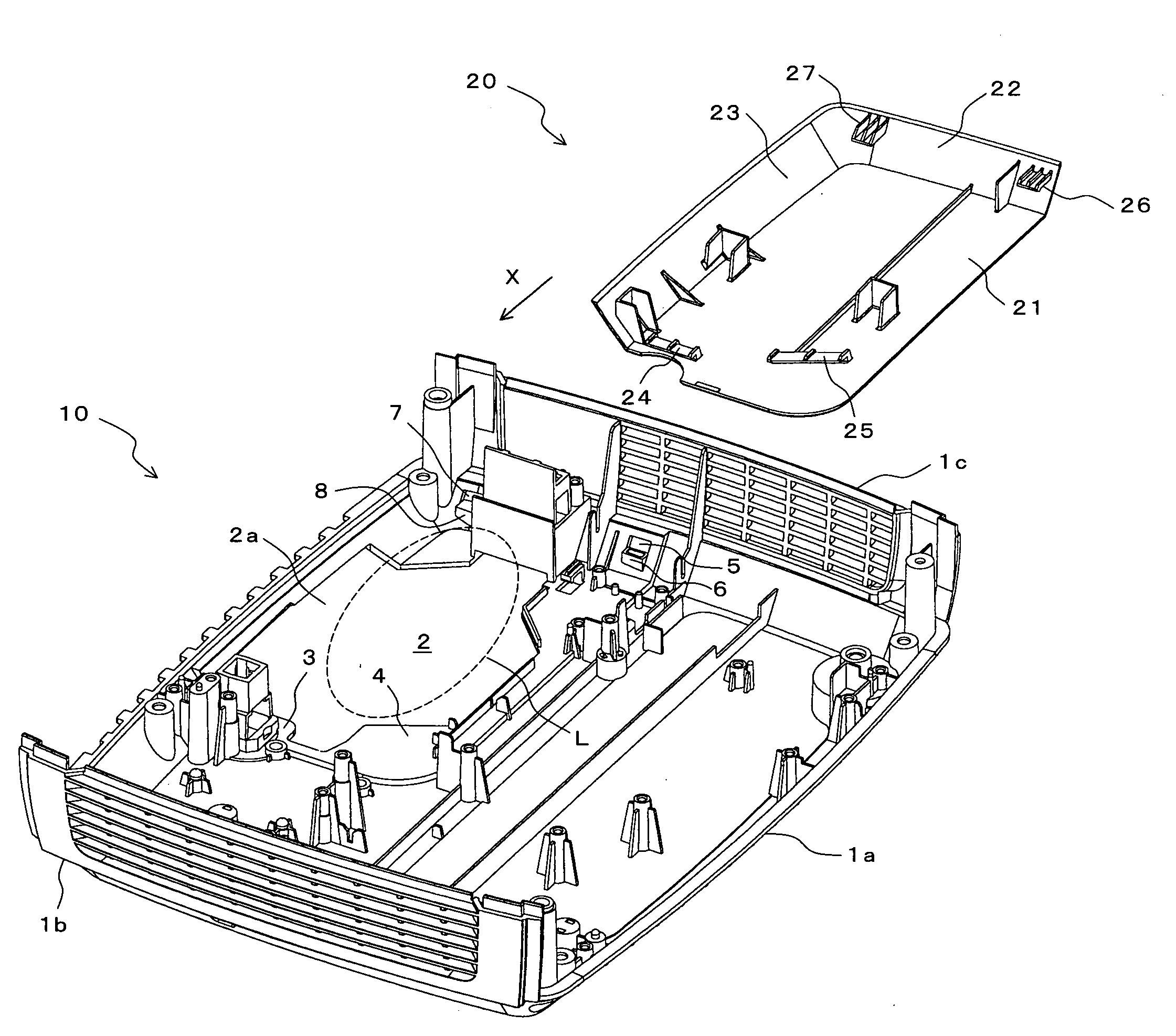
[0025]FIG. 1 is an exploded perspective view showing a housing and a lamp door of a projector according to an embodiment of the present invention. Reference numeral 10 denotes the housing of the projector, which is made of resin, and in this figure, part of the housing is shown. The housing 10 is provided with a bottom wall 1a, and side walls 1b, 1c formed on the periphery of this bottom wall 1a. In the figure, only the lower half of each of the side walls 1b, 1c is shown. Inside of the housing 10, a lamp for projection (not shown) is contained in a position indicated by broken line L of the figure. An opening 2 for lamp exchange is formed in a position corresponding to the lamp in the bottom wall 1a. Reference numeral 20 denotes the lamp door covering this opening 2, which is made of the same resin as the housing 10, and detachably attached to the housing 10 from a direction of arrow X.

[0026]The lamp door 20 is provided with a flat-plate like plate part 21 covering the opening 2, a...


PUM


Abstract

An object of the present invention is to provide a projector in which the fixing of a lamp door is prevented from being hindered by heat of a lamp, and the attachment and detachment of the lamp door can be easily performed. In a projector in which the lamp door covering an opening for lamp exchange formed in a housing is attached detachably, the lamp door includes first, second and third projected parts. The first projected part has a hook formed on the lower side of a tip end portion thereof. The housing includes a first receiving part receiving the first projected part and a second receiving part receiving the second projected part. In a state where the lamp door is attached to the housing, the first projected part of the lamp door is received by an upper surface of the first receiving part of the housing, and the hook formed in this first projected part is engaged with the first receiving part. Moreover, the second projected part of the lamp door is received by an upper surface of the second receiving part of the housing, and the third projected parts are received by upper surfaces of peripheral edges of the opening of the housing.

Description

BACKGROUND OF THE INVENTION[0001]1. Field of the Invention[0002]The present invention relates to an attaching structure for a lamp door in a projector.[0003]2. Description of the Related Art[0004]Generally, a projector is provided with a lamp as a light source, an image forming device such as liquid crystal and a DMD (digital micromirror device), an optical system leading light emitted from the lamp to the image forming device, a lens projecting an image formed by the image forming device on a screen, and the like, and these parts are contained in a housing. In the housing, an opening for exchanging the lamp is provided, and a lamp door covering this opening is detachably attached to the housing. Patent document 1, Japanese Utility Model Registration No. 3092161, Patent document 2, Japanese Patent Application Laid-Open No. 2004-347789, Patent document 3, Japanese Patent Application Laid-Open No. 2005-134575, and Patent document 4, Japanese Patent Application Laid-Open No. 2002-33366...

Claims


Application Information

Patent Timeline
IPC IPC(8): G03B21/18
CPCG03B21/2086G03B21/145
Inventor YONEZAWA, HIDEO
Owner FUNAI ELECTRIC CO LTD
Learn More