
Method of verifying system performance and performance measurement apparatus

a technology of performance measurement and system performance, applied in the direction of error detection/correction, instruments, computing, etc., can solve the problems of deteriorating load verification with respect to the system, difficulty in frequently randomly generating memory accesses from the plurality of cpus to the memory and concentrating accesses on individual control units

Inactive Publication Date: 2012-02-23
FUJITSU LTD
View PDF0 Cites 3 Cited by
  • Summary
  • Abstract
  • Description
  • Claims
  • Application Information

AI Technical Summary

Benefits of technology

The present patent application is about a program that helps measure the performance of a computer system with a storage unit and multiple control units. The program estimates the area where the address of the storage unit is set and the area where the information specifying which control unit to use is set. It then checks if the system is reliable by accessing the storage unit based on the specified information. The technical effect of this program is to improve the efficiency and reliability of computer systems with multiple control units and a storage unit.

Problems solved by technology

Therefore, in a case where the load verification with respect to the above-mentioned system is carried out, with the load generation apparatus or software, it is difficult to frequently randomly generate the memory accesses from the plurality of CPUs to the memory and concentrate the accesses on the individual control units.
Then, in the above-mentioned case, the load with respect to the control unit is decreased, and the load verification with respect to the system is deteriorated.
In the above, the case has been described in which the memory accesses from the plurality of CPUs are arbitrated by the plurality of control units, but a similar problem occurs also in a case where the memory accesses are arbitrated by the plurality of control units when the accesses are made to the storage unit such as the memory via interfaces such as a plurality of I / O channels.
In addition to that, a similar problem occurs also in another system having a function of switching the plurality of control units on the basis of the address of the access destination.

Method used


Image

  • Method of verifying system performance and performance measurement apparatus
  • Method of verifying system performance and performance measurement apparatus
  • Method of verifying system performance and performance measurement apparatus

Examples


Embodiment Construction

[0044]Hereinafter, embodiments will be described with reference to the drawings.

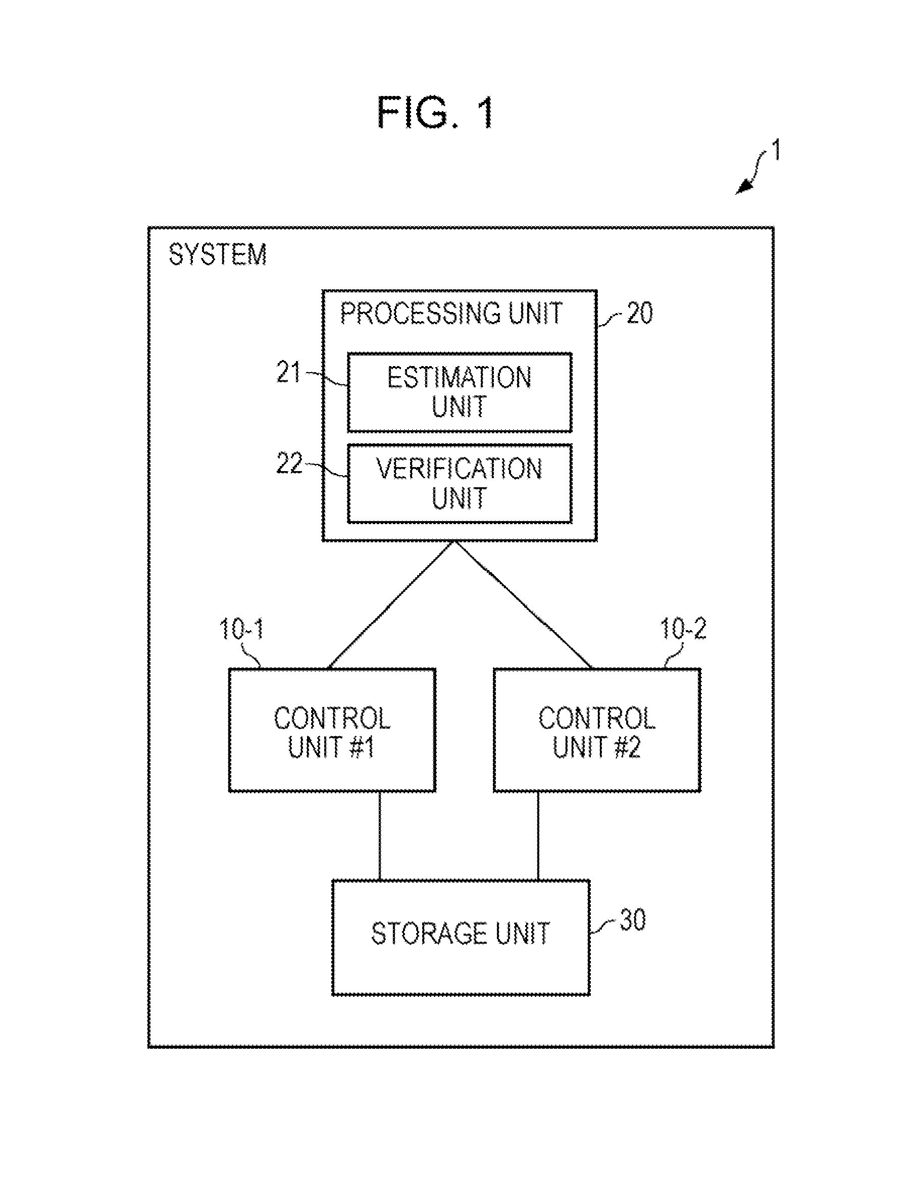
[0045]FIG. 1 is a block diagram of a configuration example of a system 1 according to a first embodiment.

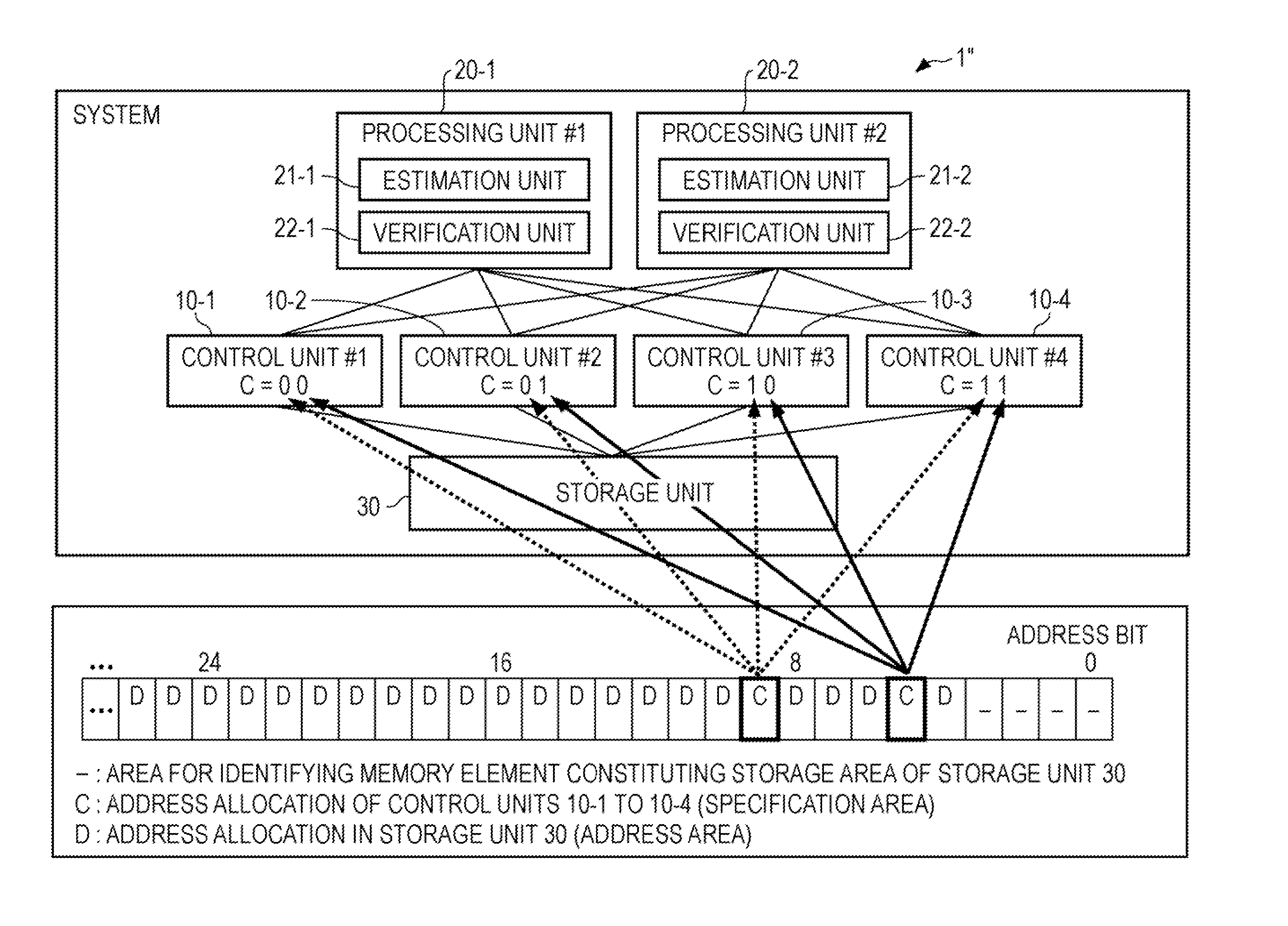
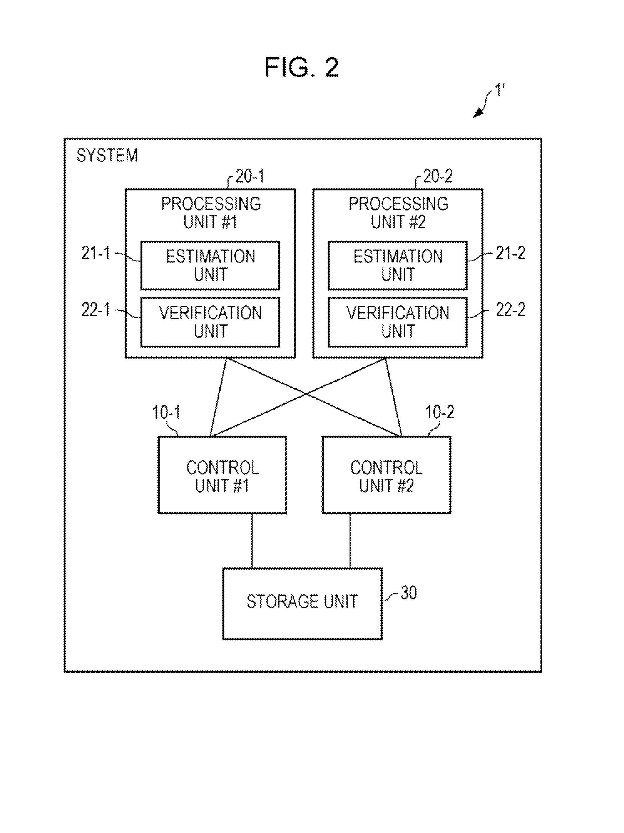
[0046]The system 1 includes plural, in an example illustrated in FIG. 1, two control units 10-1 and 10-2, a processing unit 20, and a storage unit 30.

[0047]The control units 10-1 and 10-2 are adapted to arbitrate accesses from the processing unit 20 to the storage unit 30.

[0048]The control units 10-1 and 10-2 are verification targets of an apparatus verification program according to the present embodiment.

[0049]For the control units 10-1 and 10-2, for example, a system controller is exemplified. Hereinafter, a case will be described in which system controllers are used for the control units 10-1 and 10-2. However, the embodiment is not limited to this, and instead of the system controllers, another apparatus having a function of arbitrating accesses from the processing unit 20 to the storage unit 30 m...


PUM


Abstract

A computer-readable, non-transitory medium storing a program for measuring a performance in a system including a storage unit and a plurality of control units for controlling an access to the storage unit, the program causing a computer to execute a procedure, the procedure includes estimating a specification area in address information including an address area in which an address of an access target of the storage unit is set and the specification area in which specification information for specifying a control unit for controlling an access to the access target is set, and verifying a reliability of the system by accessing the storage unit on the basis of a specification information in the specification area.

Description

CROSS-REFERENCE TO RELATED APPLICATION[0001]This application is based upon and claims the benefit of priority of the prior Japanese Patent Application No. 2010-183787 filed on Aug. 19, 2010, the entire contents of which are incorporated herein by reference.FIELD[0002]The embodiments discussed herein related to a method of verifying a system performance and a performance measurement apparatus.[0003]BACKGROUND[0004]FIG. 18 is a block diagram of a configuration example of an information processing system. A system 100 illustrated in FIG. 18 is provided with a control unit 110, a CPU (Central Processing Unit) 120, a memory 130, and an I / O (Input / Output) channel 140.[0005]The control unit 110 is adapted to arbitrate memory accesses from the CPU 120 or the I / O channel 140 to the memory 130, and, for example, a system controller is exemplified.[0006]In case where a load verification is carried out with respect to the system 100 illustrated in FIG. 18, in a load generation apparatus or soft...

Claims


Application Information

Patent Timeline
Patent Type & Authority Applications(United States)
IPC IPC(8): G06F12/00
CPCG06F11/3428G06F11/3414
Inventor SUZUKI, SHINTAROU
Owner FUJITSU LTD
Learn More