
Five axis machine vise

a five-axis machine and vise technology, applied in the field of vise, can solve the problems of not providing a vise, difficult to keep the prior device clean and free of chips, etc., and achieve the effects of preventing substantial deflection, preventing deflection of the support of the jaws, and precise machining

Active Publication Date: 2012-02-23
KURT MANUFACTURING COMPANY INC
View PDF17 Cites 18 Cited by
  • Summary
  • Abstract
  • Description
  • Claims
  • Application Information

AI Technical Summary

Benefits of technology

"The present invention is a five axis vise that has two separated parts that are mounted on a support. The vise body parts are secured in place using capscrews and T-nuts. A vise screw or tension link is mounted on one of the vise body parts and engages a movable jaw assembly. The vise body parts have clamping jaws that are spaced above the support surface. The movable jaw slides along rails on the other vise body part and as the tension in the tension link increases, the movable jaw will be brought into clamping engagement with a work piece and the angled engaging surfaces between the jaw nut and moveable jaw will also create a down pressure on the movable jaw to prevent substantial deflection. The prevention of deflection of the support for the jaws aids in precise machining. The hub at the end of the vise screw provides a relatively large surface for supporting and guiding the screw and suitable thrust washers and bearings are used to react the end thrust on the hub when the screw is tightened to clamp a work piece. The first vise body forms a fixed jaw."

Problems solved by technology

Prior devices are difficult to keep clean and free of chips, and do not provide a vise which actuates the movable jaw through angled surfaces that create a down force on the movable jaw.

Method used


Image

  • Five axis machine vise
  • Five axis machine vise
  • Five axis machine vise

Examples


Embodiment Construction

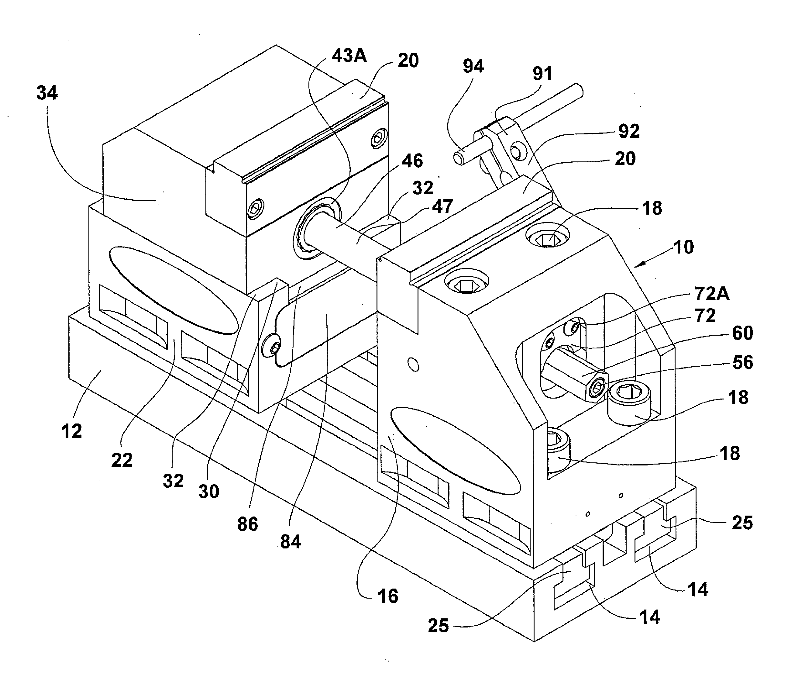
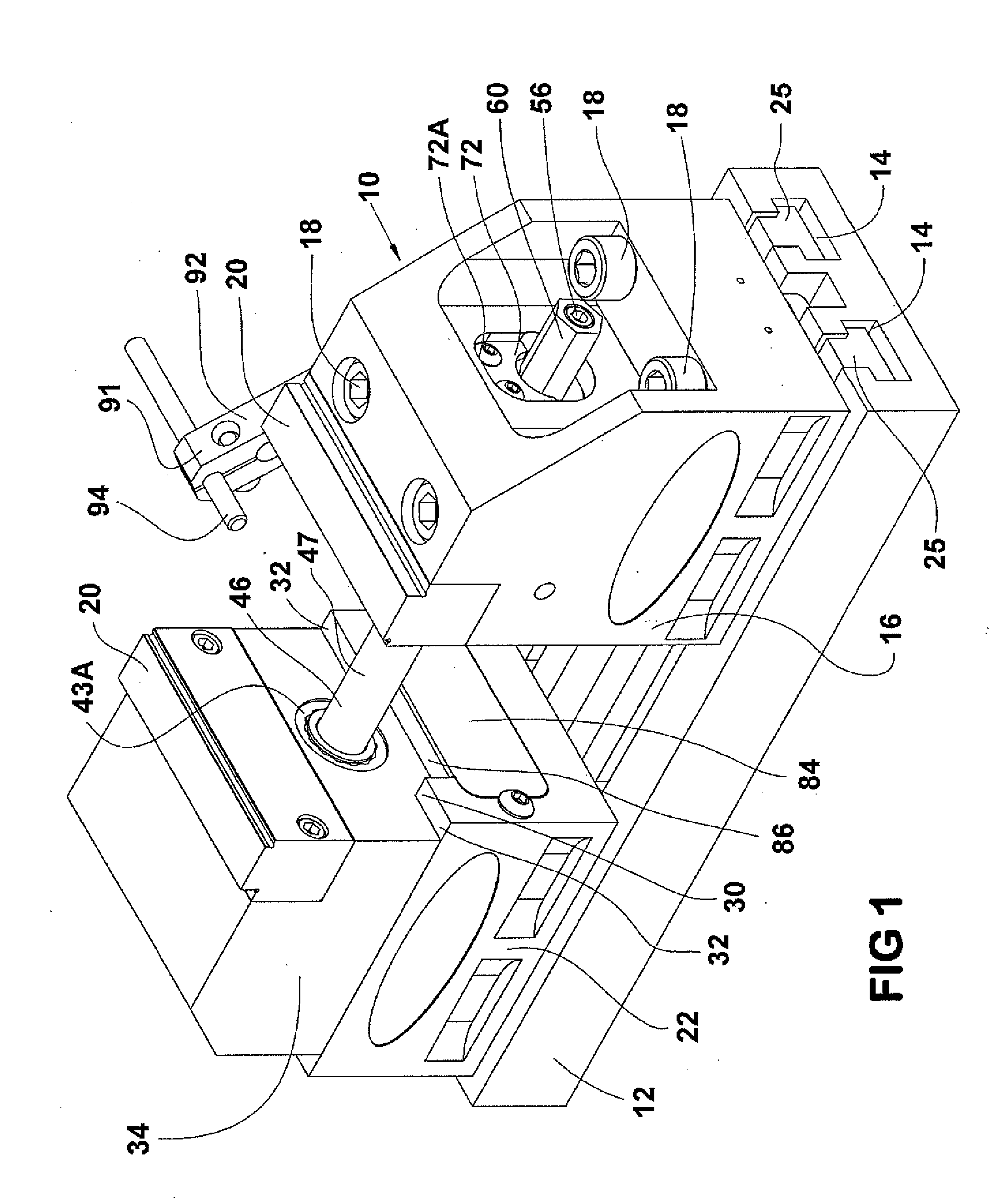
[0017]FIG. 1, a five axis vise assembly indicated generally 10 is shown mounted on a support, schematically illustrated as a machine tool table 12. The vise assembly is mounted in the “T” slots 14 of such a machine tool table as is conventionally done. The vise assembly 10 includes a first fixed jaw vise body portion 16 that is fixed in position on the tool table 12 along the longitudinal direction of the T-slots 14 using suitable capscrews 18, and T-slot nuts 25 (FIG. 4). The fixed jaw vise body portion 16 has a jaw plate 20 at an upper corner thereof that faces a second movable jaw vise body portion 22, also held in place on the tool table 12 with cap screws 24 (see FIG. 4) and T slot nuts 25.

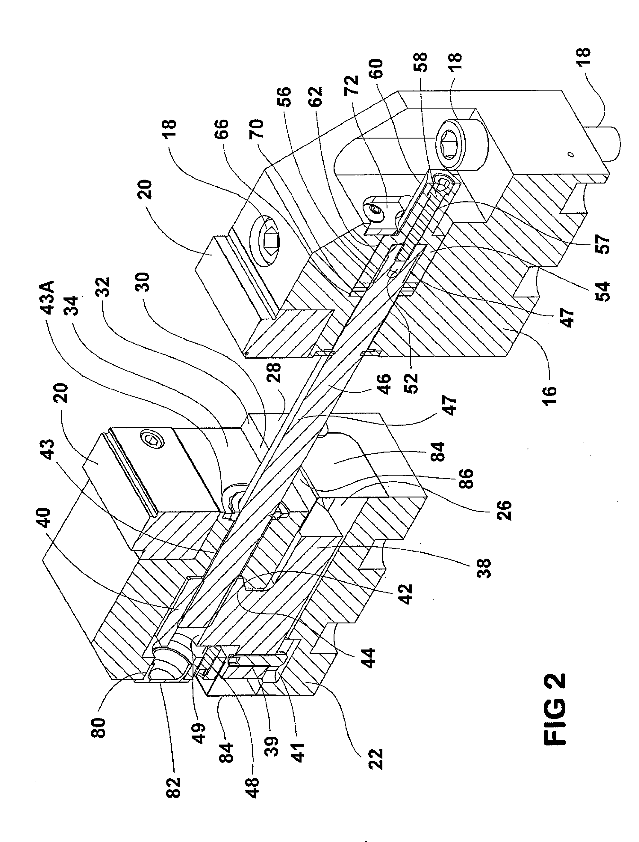
[0018]The vise body portions 16 and 22 can be held very securely, and as shown their facing surfaces are spaced apart. The vise body portion 22 is provided with a central longitudinal channel 26 that extends along the longitudinal length of the vise body portion 22, and is defined by upright ...


PUM


Abstract

A five axis vise includes two separated vise body portions that are supported on a machine tool table or other support that fixes the vise body portions in position. The vise body portions have jaws spaced up from the machine tool table sufficiently to permit machining five surfaces of a work piece held in the jaws. A vise screw is rotatably mounted in one of the vise body portions, and extends to the other vise body portion to actuate a movable jaw on the other vise body portion. The vise screw is threaded into a jaw nut that has a drive surface that engages and drives a driven surface on the movable jaw, with the drive and driven surfaces being inclined relative to the axis of force application to provide a downward force component on the movable jaw as it is tightened. The vise screw is an assembly of a threaded shank or shaft and a hub that is rotatably mounted in one of the body portions, with the threaded shank or shaft being locked in position in the hub.

Description

CROSS REFERENCE TO RELATED APPLICATION[0001]This application refers to and claims priority to U.S. Provisional Patent Application Ser. No. 61 / 374,656, filed Aug. 18, 2010, the content of which is incorporated by reference.BACKGROUND OF THE DISCLOSURE[0002]This disclosure relates to a vise that will permit machining on several sides of a work piece and which has two spaced vise body portions rigidly held on a support, such as a machine tool table. A movable jaw on one of the vise body portions is actuated by a jaw nut acting on the movable jaw through angled mating surfaces to provide down pressure on the jaw as the part is clamped and to do so with minimum deflection of the vise portions.[0003]In the work holding and vise industry, the term “five axis vise” refers to a vise that allows five-sided machining, such as five sides of a cube without removing the part from the vise. This means the part must be elevated from the machine bed or table sufficiently to provide for a horizontal ...

Claims


Application Information

Patent Timeline
Patent Type & Authority Applications(United States)
IPC IPC(8): B25B1/10B25B1/24
CPCB25B1/103B25B1/2468B25B1/2484B25B1/2473
Inventor SCHMIDT, DAVID L.
Owner KURT MANUFACTURING COMPANY INC
Learn More