
Method and Device for Generating and Storing Hydrogen

a technology of hydrogen generation and storage, applied in the direction of electrolysis process, electrolysis components, reactant parameter control, etc., can solve the problems of metal hydride being soon spoiled, the danger of system blocking by freezing is negligible, and the time interval for a replacement of chemical absorbers is larg

Inactive Publication Date: 2012-02-23
SHANGHAI HORIZON FUEL CELL TECH
View PDF4 Cites 7 Cited by
  • Summary
  • Abstract
  • Description
  • Claims
  • Application Information

AI Technical Summary

Benefits of technology

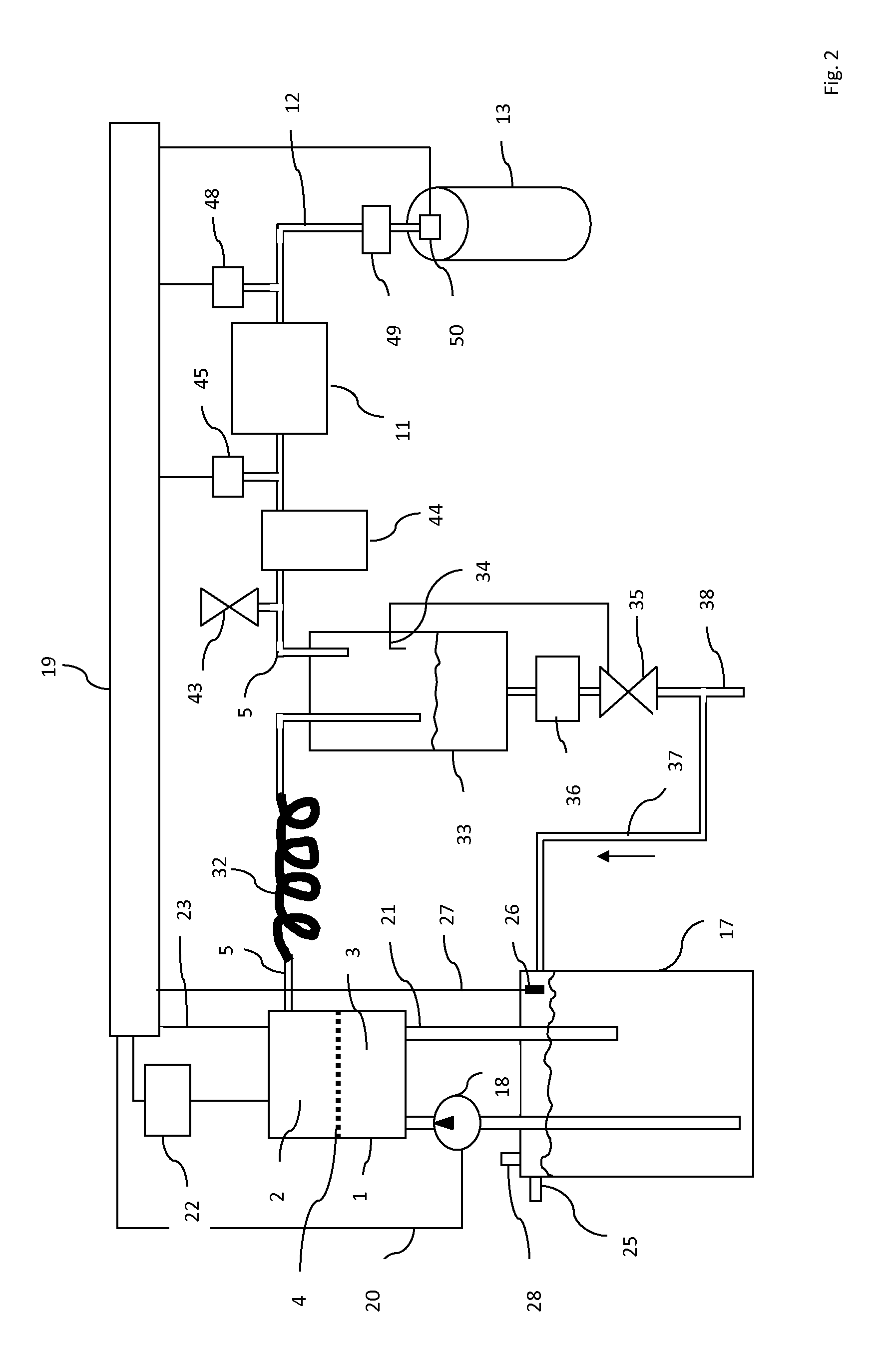
[0007]Additional dehydrating means such as water vapour separators in the form of a chemical absorber can advantageously be added. The time intervals for a replacement of the chemical absorber are large due to the poor total water vapour produced by the electrolyser. Further a liquid water separator such as a condenser working through cooling to ambient temperature or below can be integrated. The danger of system blocking by freezing is negligible due to the low water content as a result of the high first pressure. The liquid water separator contains a gas collecting area and a liquid collecting area, the latter comprising a liquid level sensor controlling a liquid exhaust which contains a pressure reducer and a valve. The collected liquid can be exhausted or recycled to the electrolysis cell or cells. This can guarantee a continuous operation.

Problems solved by technology

If the hydrogen-water mixture is fed into the metal hydride store as generated with 0.1 MPa, the metal hydride will soon be spoiled.
The time intervals for a replacement of the chemical absorber are large due to the poor total water vapour produced by the electrolyser.
The danger of system blocking by freezing is negligible due to the low water content as a result of the high first pressure.

Method used


Image

  • Method and Device for Generating and Storing Hydrogen
  • Method and Device for Generating and Storing Hydrogen
  • Method and Device for Generating and Storing Hydrogen

Examples


Embodiment Construction

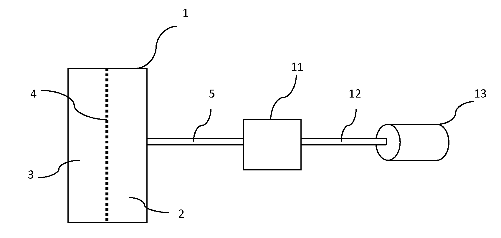
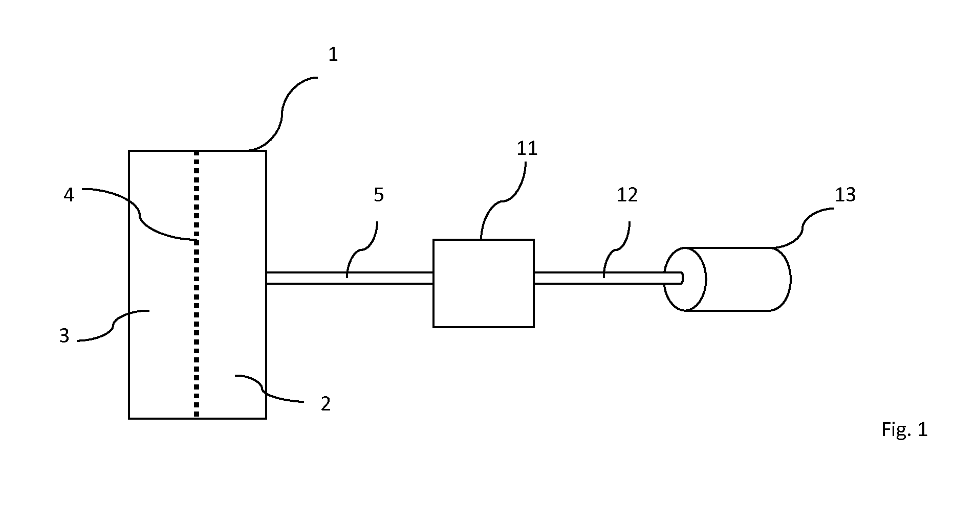
[0014]According to FIG. 1, in a stack of PEM electrolysis cells 1, in the drawing for simplicity shown as a single cell, a cathode compartment 2 and an anode compartment 3 are separated by a polymer electrolyte membrane (PEM) 4. To the anode compartment 3, in operation water is added. The compartments contain electrodes to which dc is supplied, whereupon at the anode in compartment 3 oxygen is produced and at the cathode in compartment 2 hydrogen is produced, which is the used product of the electrolysis cells 1. The hydrogen is generated under a pressure of at least 1 MPa, preferably 2.5 to 4 MPa under which pressure hardly any water vapour, escapes with the hydrogen. In this case, hardly any contaminating water will emerge in the cathode compartment 2.

[0015]From this compartment 2, a first conduit 5 conducts the hydrogen, nearly without any water content, under the original high pressure to a pressure adjusting device 11, which, in the described example, is a pressure reduction va...


PUM

PropertyMeasurementUnit
pressureaaaaaaaaaa
temperatureaaaaaaaaaa
counter pressureaaaaaaaaaa

Abstract

A method and device for charging a metal hydride hydrogen store (13) is described. It comprises generating gaseous hydrogen in an electrolyser (1), transporting the gaseous hydrogen to the metal hydride store and feeding the metal hydride store with the hydrogen. For having the hydrogen free of water contamination, the gaseous hydrogen is first transported under a first pressure of at least 1 MPa which pressure is then reduced by a pressure adjusting means (11) to a second, designated pressure lower to the first pressure, the second pressure being the feeding pressure to the metal hydride store. FIG. 1.

Description

FIELD OF THE INVENTION[0001]The invention relates to a method and a device for generating and storing hydrogen, particularly for providing a hydrogen source for fuel cells, the method comprising the steps of generating gaseous hydrogen in an electrolyser, transporting the gaseous hydrogen to the metal hydride store and feeding the metal hydride store with the hydrogen.BACKGROUND OF THE INVENTION[0002]Hydrogen storage via a metal hydride, e.g. LaNi or TiZr based alloys with AB2 or AB5 structure respectively is a known method for providing a hydrogen supply for consumers such as fuel cells. Metal hydrides, however, are very sensitive to water in both a liquid and vapour form. Hydrogen generated by electrolysis typically contains fractions of water which must be eliminated before reaching the metal hydride store.[0003]It is known, e.g. from U.S. Pat. No. 5,964,089, FIG. 3, to eliminate the water fraction by a liquid water trap, a condensing coil and a chemical drier. For a complete eli...

Claims


Application Information

Patent Timeline
Patent Type & Authority Applications(United States)
IPC IPC(8): C25B1/02C25B15/00C25B9/08C25B9/19
CPCC25B1/12Y02E60/366H01M8/04216Y02E60/36Y02E60/50C25B1/04C25B9/05
Inventor GU, ZHIJUNYANG, ZHENG
Owner SHANGHAI HORIZON FUEL CELL TECH
Learn More