
Pipe Cleaning Apparatus

a cleaning apparatus and pipe technology, applied in the direction of cleaning process and apparatus, hair cleaning, hair equipment, etc., can solve the problems of limiting the heat transfer efficiency and life expectancy of the tubing, reducing and prone to accumulation on the inner surface of the heat exchanger tubing or piping. , to achieve the effect of increasing or decreasing the length of the pipe cleaning apparatus

Inactive Publication Date: 2012-02-23
ITC LIMITED
View PDF3 Cites 9 Cited by
  • Summary
  • Abstract
  • Description
  • Claims
  • Application Information

AI Technical Summary

Benefits of technology

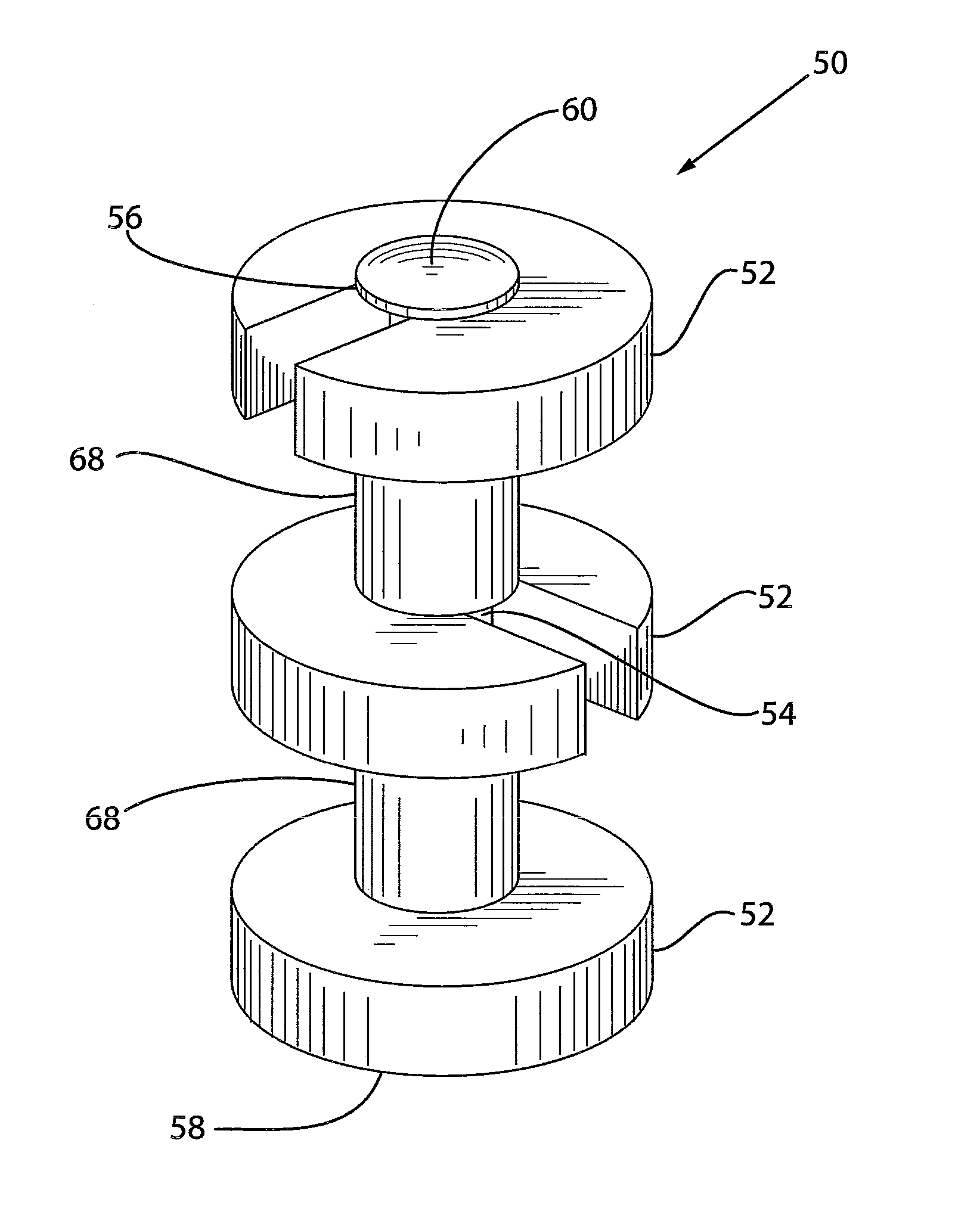
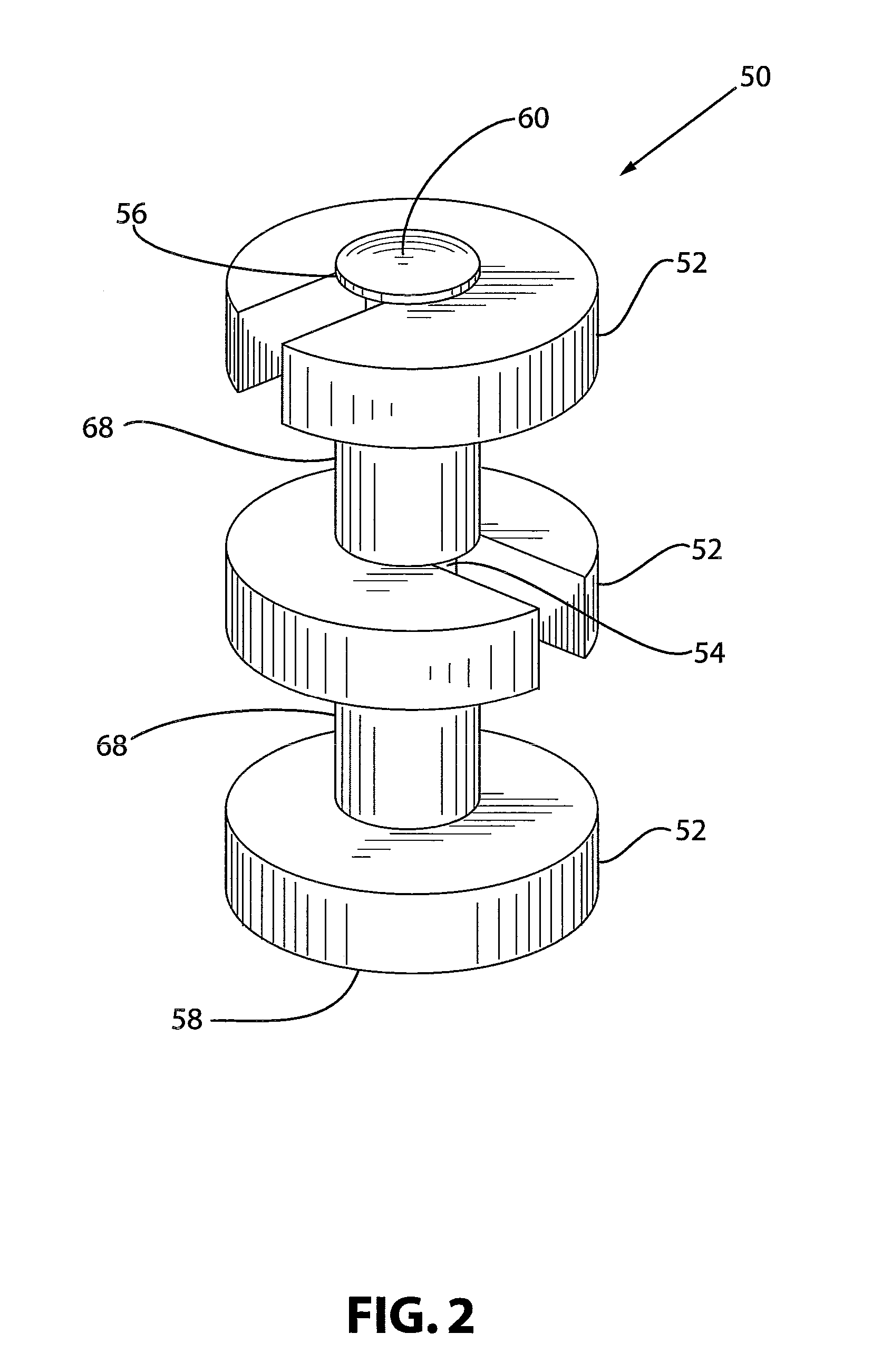
[0016]In accordance with another embodiment of the pipe cleaning apparatus, diameter of the central opening of each scraper is preferably slightly larger than the diameter of the shaft to allow the scraper to slide along the shaft. Each spacer may have a central hole extending along a central axis of the spacer. Similar to the scraper structure, diameter of the central hole may be slightly larger than the diameter of the shaft to allow the spacer to slide along the shaft. Each scraper and spacer may be independently rotatable about the longitudinal axis of the shaft. Additionally, each spacer is desirably uniform in length to maintain the scrapers substantially equidistant to each other.

Problems solved by technology

Inner surface of heat exchanger tubing or piping is prone to accumulating sediment from the liquid medium.
Accumulation of sediment from the liquid medium presents many problems, such as deposits and obstructions, which limit heat transfer efficiency and life expectancy of the tubing.
A properly cleaned inner surface of the tube yields increased heat exchanger and condenser efficiency and prolongs the life expectancy of the tubing.
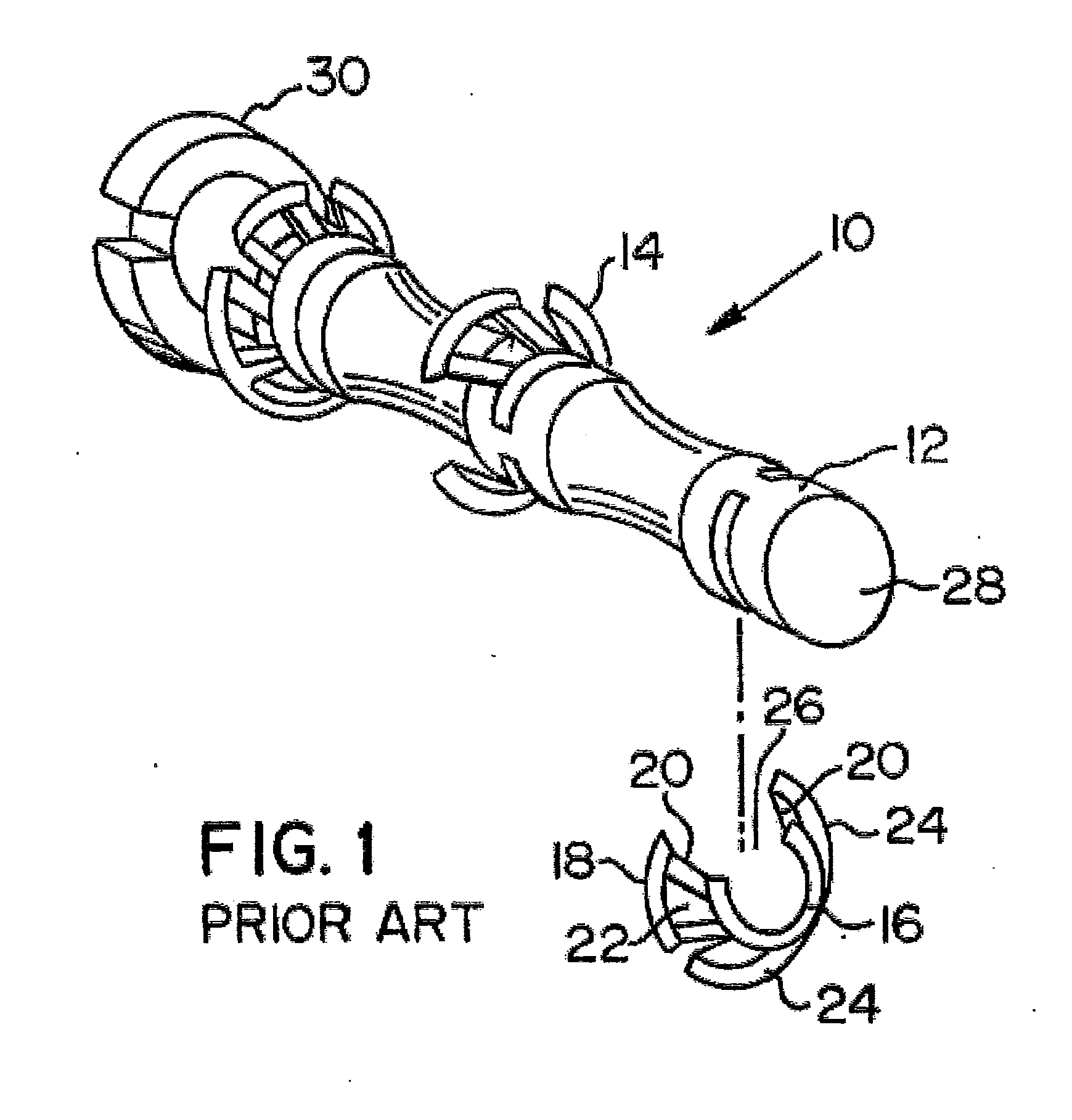
Although the pipe cleaning assembly 10 works well, it must be preassembled which requires a substantial amount of labor costs.
Numerous other disadvantages are associated with the prior art designs.
Prior art embodiments that utilize metal scraper blades are expensive to manufacture because of their non-circular shape, often resulting in a high manufacturing rejection rate.
Furthermore, existing designs cannot be easily repaired in the field, which can further extend the downtime of a heat exchanger or condenser system.
Additionally, scraper blades made from plastic or polymeric materials are often highly flexible, which causes them to deflect over sediments rather than dislodge them from the inside surface of the tube.

Method used


Image

  • Pipe Cleaning Apparatus
  • Pipe Cleaning Apparatus
  • Pipe Cleaning Apparatus

Examples


Embodiment Construction

[0027]For purposes of the description hereinafter, spatial orientation terms, if used, shall relate to the referenced embodiment as it is oriented in the accompanying drawing figures or otherwise described in the following detailed description. However, it is to be understood that the embodiments described hereinafter may assume many alternative variations and embodiments. It is also to be understood that the specific devices illustrated in the accompanying drawing figures, and described herein, are simply exemplary and should not be considered as limiting. Additionally, terms “pipe”, “piping”, “hose”, “tube”, or “tubing” may be used interchangeably in reference to an annular conduit typically utilized in heat exchanger and condenser systems.

[0028]Referring to the drawings in which like reference characters refer to like parts throughout the several views thereof, the present invention is generally described in terms of a pipe cleaning apparatus for use in cleaning heat exchanger an...


PUM


Abstract

A pipe cleaning apparatus for cleaning pipes or tubes includes a plurality of scrapers and a plurality of spacers secured to a shaft. Each scraper includes a scraper body with an outer perimeter defining a scraper blade adapted to contact an inner surface of a tube and at least one radial slot defined by the body. Each of the scrapers and spacers are inserted onto a cylindrical shaft. Each spacer is sandwiched between two adjacent scrapers. The scrapers are adapted to contact an inner surface of a tube or a pipe.

Description

CROSS REFERENCE TO RELATED APPLICATION[0001]This application claims priority to U.S. Provisional Patent Application No. 61 / 374,355, filed Aug. 17, 2010, entitled “Pipe Cleaning Apparatus”, the entire disclosure of which is herein incorporated by reference.BACKGROUND OF THE INVENTION[0002]1. Field of the Invention[0003]The present invention generally relates to the field of pipe cleaning devices and, more particularly, to plug assemblies operative for cleaning an inner surface of heat exchanger and condenser tubing or piping.[0004]2. Description of the Related Art[0005]Heat exchanger systems typically have a plurality of tubes or pipes through which a liquid cooling or heating medium, such as water, flows to remove heat from, or add heat to, an industrial process or the like. Inner surface of heat exchanger tubing or piping is prone to accumulating sediment from the liquid medium. Accumulation of sediment from the liquid medium presents many problems, such as deposits and obstruction...

Claims


Application Information

Patent Timeline
IPC IPC(8): B08B9/045B08B1/04
CPCB08B9/057
Inventor ANTAL, MICHAEL P.ANTAL, BRIAN
Owner ITC LIMITED
Learn More