
Vehicle detection apparatus

Active Publication Date: 2012-02-02
KOITO MFG CO LTD
View PDF16 Cites 17 Cited by
  • Summary
  • Abstract
  • Description
  • Claims
  • Application Information

AI Technical Summary

Benefits of technology

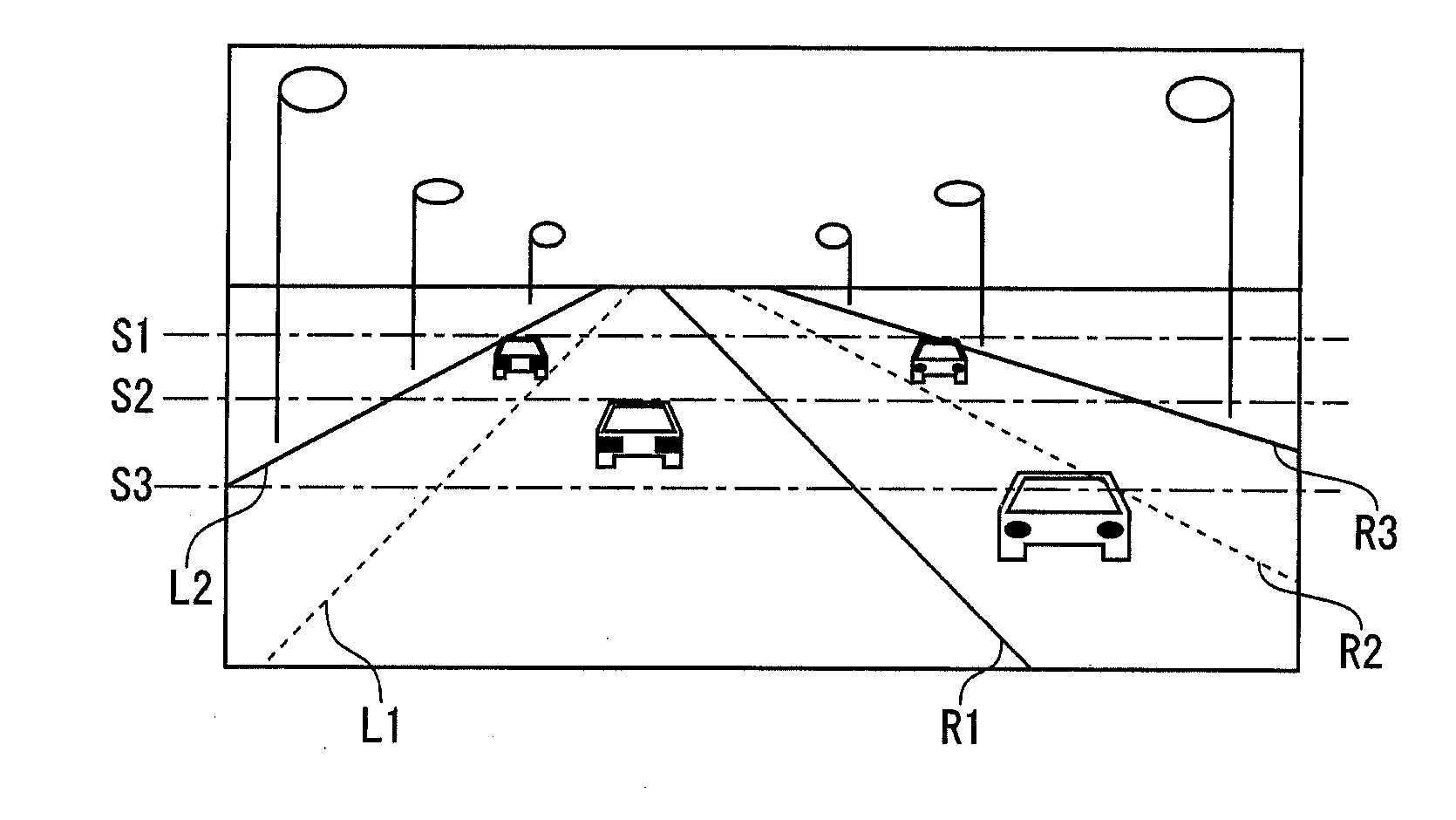
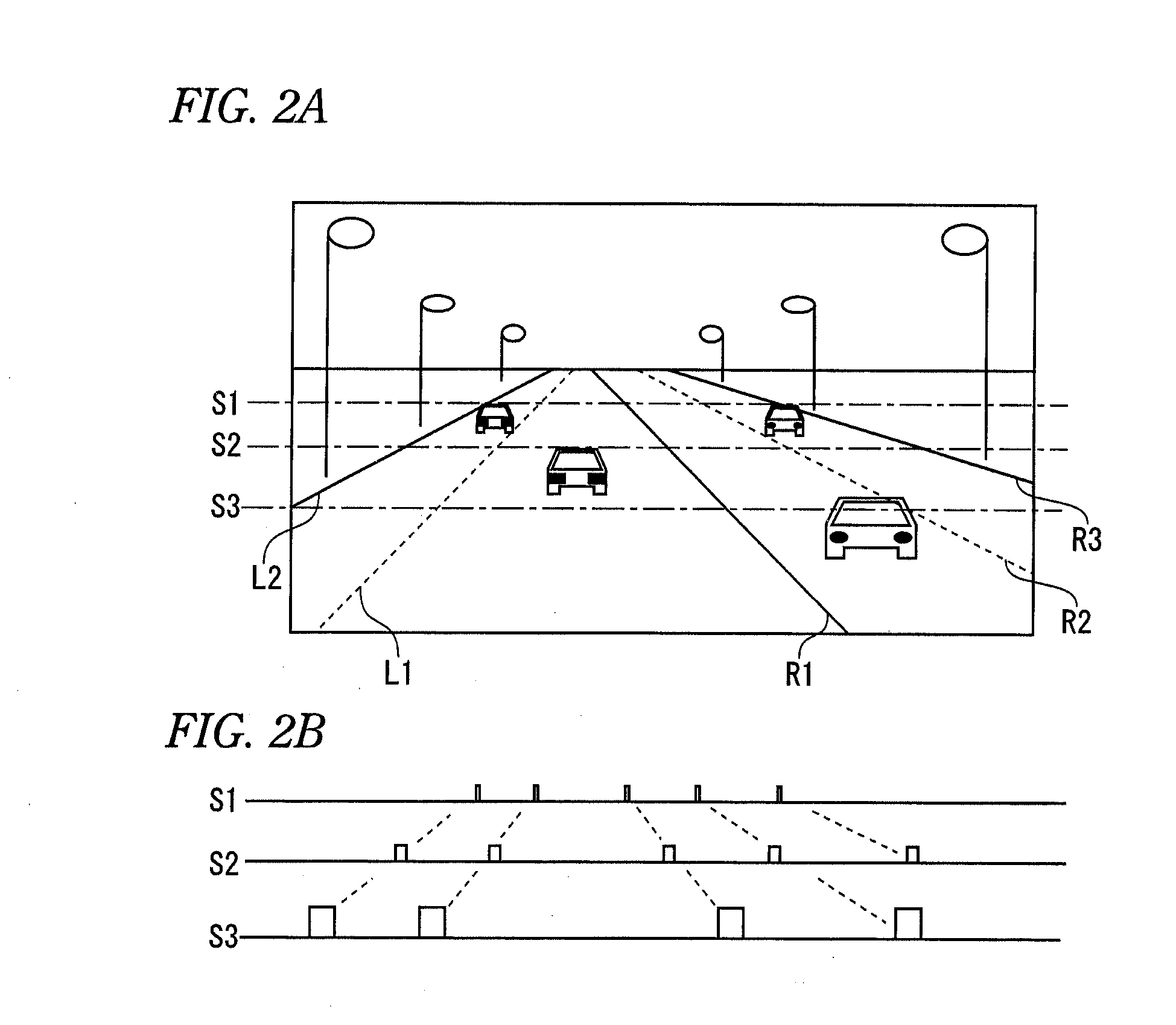
[0012]In some implementations, the vehicle detection apparatus detects vehicle lane-lines in a captured image, and based on the detected vehicle lane-line, divides the captured image into an own vehicle lane region, an oncoming vehicle lane region, and a vehicle lane exterior region (road shoulder region). The likelihood of detecting a vehicle ahead, an oncoming vehicle and a stationary light can accordingly be raised in each of the regions. By setting detection conditions such that prioritized detection is performed for objects in each of the regions with high detection likelihoods, detection of each of the respective detection objects can be accomplished quickly. It also is possible to reduce false detections. Other aspects, features and advantages will be apparent from the following detailed description, the accompanying drawings and the claims.

Problems solved by technology

However, a high beam light distribution can sometimes dazzle the driver of a vehicle ahead or the driver of an oncoming vehicle present in the region in front of the vehicle itself.
However, such a method requires that such a determination be performed for all of the points of light in the captured image, which results in a large number of data points for processing, and an extreme load for determination processing.
This makes it difficult to detect a vehicle ahead or an oncoming vehicle quickly, and consequently also makes it difficult to control in real-time the light distribution from the headlights of the vehicle itself.
Furthermore, a problem arises because falsely detecting even a single detected attribute makes it difficult to discriminate between a vehicle illumination device and a stationary light, thus lowering the detection accuracy of other vehicles.

Method used


Image

  • Vehicle detection apparatus
  • Vehicle detection apparatus
  • Vehicle detection apparatus

Examples


Embodiment Construction

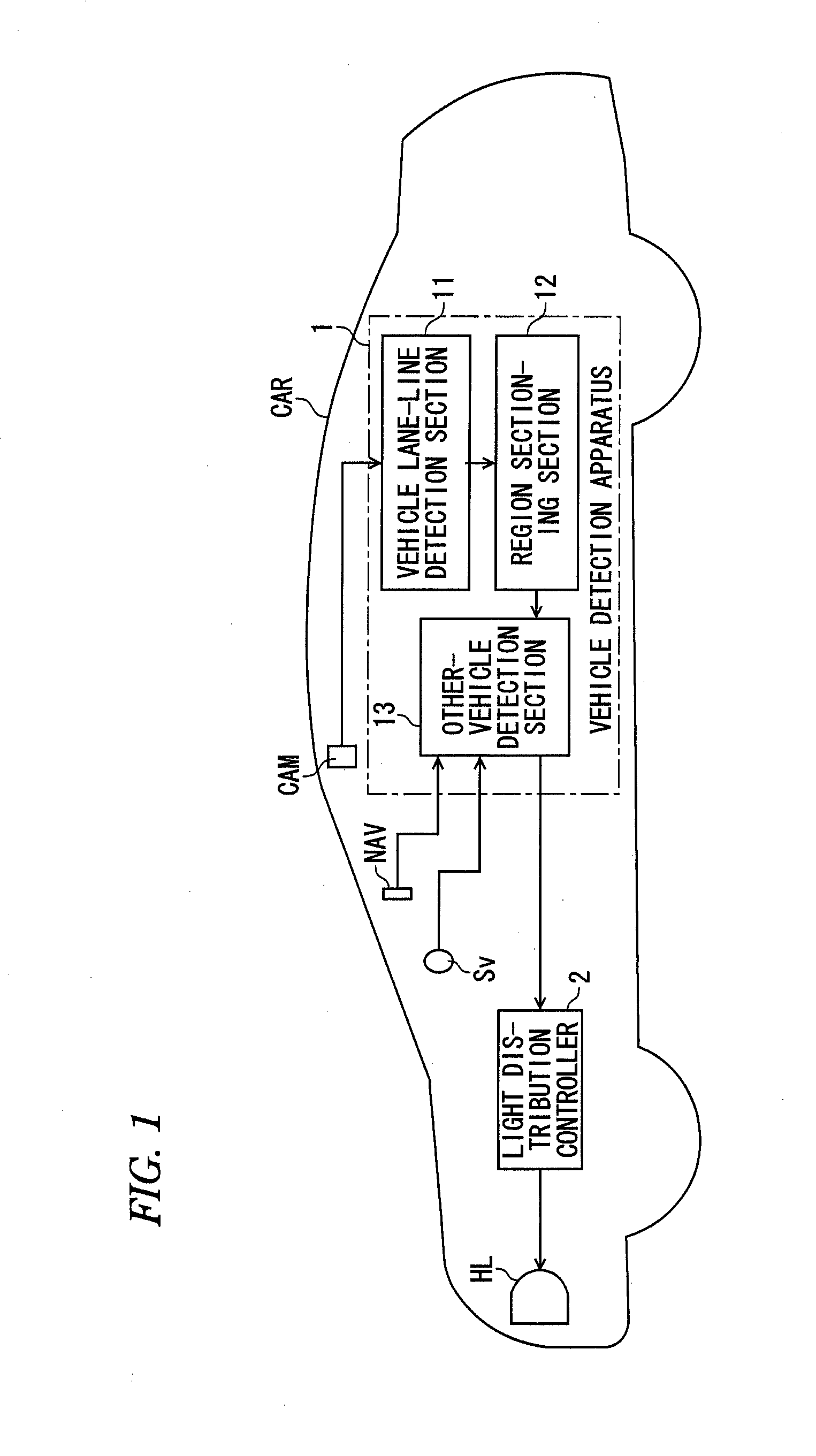
[0019]The following explanation describes an exemplary embodiment, with reference to the drawings. FIG. 1 is a schematic configuration diagram in which an example of a vehicle detection apparatus of the invention is applied to a headlight control apparatus for controlling light distribution of a headlight. A vehicle CAR is mounted with an imaging camera CAM for capturing an image of a region in front of the vehicle itself, and a vehicle detection apparatus 1 for detecting other vehicles based on the image obtained with the imaging camera CAM. The vehicle detection apparatus 1 includes a light distribution controller 2 that serves as a headlight control device for controlling the light distribution of the headlights HL used for illuminating a region in front of the vehicle itself according to other vehicle detection by the vehicle detection apparatus 1.

[0020]The headlights HL can be switched between a high beam light distribution and a low beam light distribution under control of the...


PUM


Abstract

A vehicle detection apparatus comprises an other-vehicle detection module configured to detect points of light in an image captured by a vehicle to which the vehicle detection module is mounted and to detect other vehicles based on the points of light, a vehicle lane-line detection module configured to detect an vehicle lane-line in the captured image, and a region sectioning module configured to section the captured image based on the detected vehicle lane-line into an own vehicle lane region, an oncoming vehicle lane region, and a vehicle lane exterior region. Other vehicles are detected by the other-vehicle detection module by detecting points of light based on respective detection conditions set for each of the sectioned regions.

Description

CROSS REFERENCE TO RELATED APPICATION(S)[0001]This application claims the benefit of priority of Japanese Patent Application No. 2010-167988, filed on Jul. 27, 2010, the disclosure of which is incorporated by reference herein.TECHNICAL FIELD[0002]Embodiments described herein relate to a vehicle detection apparatus that detects other vehicles based on an image captured of a region in front of a vehicle installed with the vehicle detection apparatus.RELATED ART[0003]Illumination with a high beam light distribution is desirable for the headlights of a vehicle, such as a car, for the purpose of increasing visibility in a region in front of the vehicle. However, a high beam light distribution can sometimes dazzle the driver of a vehicle ahead or the driver of an oncoming vehicle present in the region in front of the vehicle itself. To address this issue, technology is proposed in Japanese Patent Document JP-A-2008-37240 for securing visibility in the region in front of a vehicle while al...

Claims


Application Information

Patent Timeline
IPC IPC(8): G06K9/00
CPCG06K9/00825G06K9/00798G06V20/588G06V20/584
Inventor ENDO, OSAMU
Owner KOITO MFG CO LTD
Learn More