
High speed scanning of large objects using radiation

a radiation and large object technology, applied in the field of high-speed radiation scanning of large objects, can solve the problems of large indirect financial loss, increased cost, and down the commerce, and achieve the effects of low cost, easy fit, and low heigh

Inactive Publication Date: 2012-02-02
SINGH SATPAL
View PDF3 Cites 7 Cited by
  • Summary
  • Abstract
  • Description
  • Claims
  • Application Information

AI Technical Summary

Benefits of technology

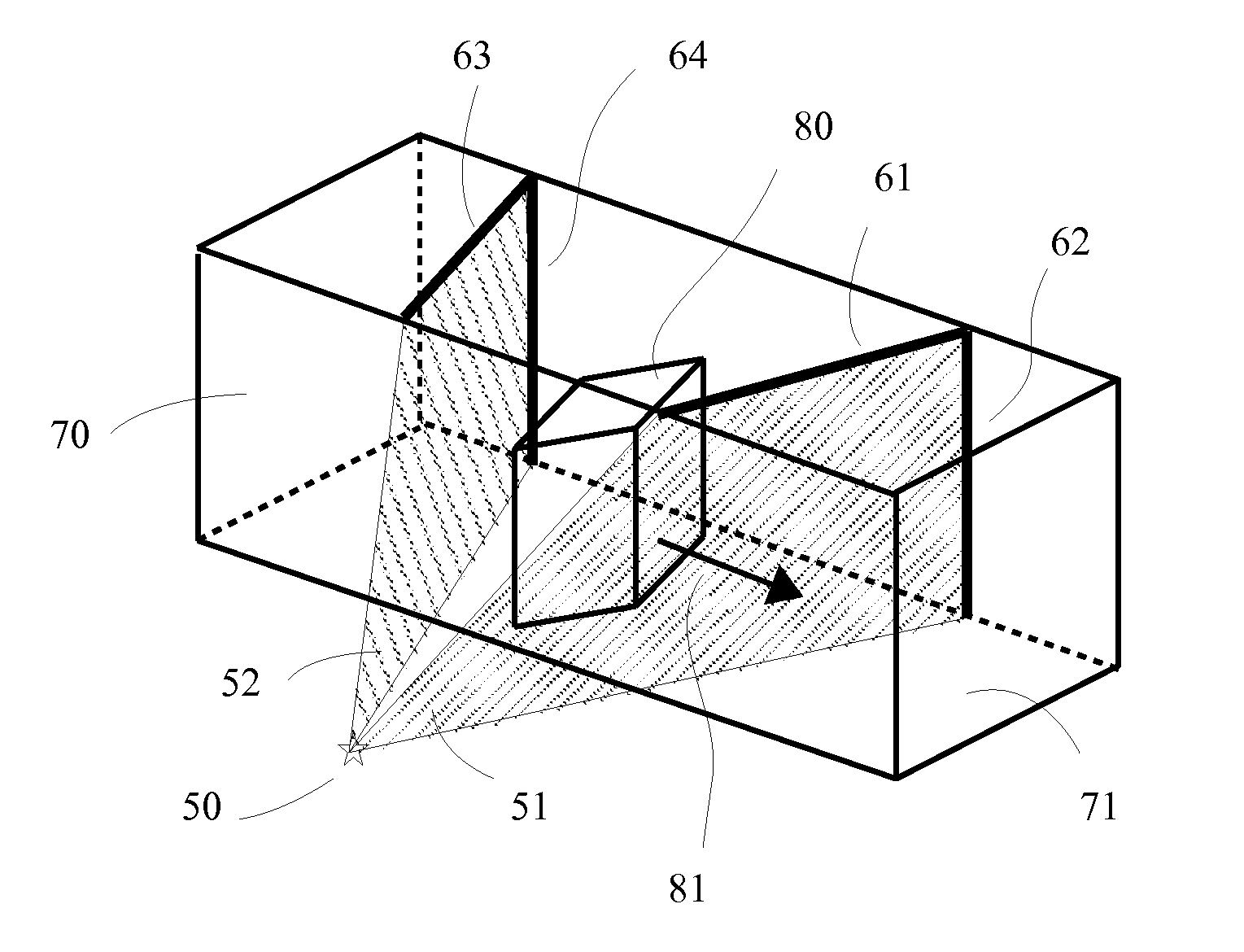
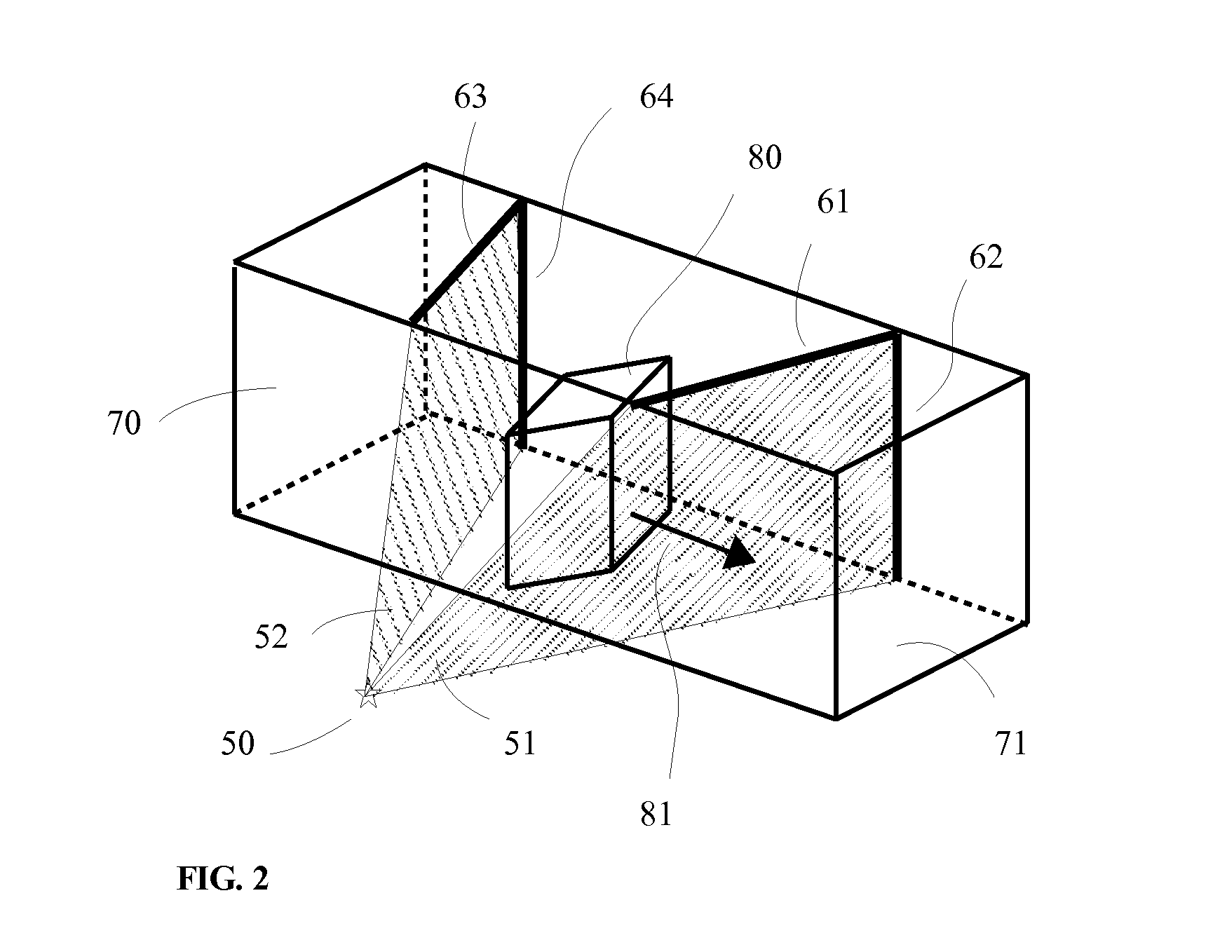
The invention is a dual view x-ray system for inspecting cargo. It uses a unique beam arrangement to quickly scan tall, palletized cargo that can fit in rooms with low ceilings. The system is low-cost because it uses a single x-ray source. The object is rotated 45 degrees before being translated through a tunnel, which minimizes the path of the x-rays and reduces absorption by the object. The x-ray source is placed near the floor and emits radiation in a horizontal direction. This arrangement results in high-speed scans for objects taller than their transverse dimensions. The invention has several advantages, including low height and low cost.

Problems solved by technology

Often a single scan image thus obtained is not sufficient to examine the contents of the cargo, therefore a second source of x-ray is used that directs it beam at ninety degrees to the first to get a second view of the object.
This slows down the commerce and results in large indirect financial loss.
This results in extra cost.
Another problem with dual source x-ray systems with the second source located on top of the tunnel is that the height of the scanning machine is large.
This is higher than most ceilings which are just 8 feet, therefore the use of such machines often requires facilities modifications which results in a substantial additional or installation costs.

Method used


Image

  • High speed scanning of large objects using radiation
  • High speed scanning of large objects using radiation
  • High speed scanning of large objects using radiation

Examples


Embodiment Construction

[0022]In describing the preferred embodiment and its alternatives, specific terminology will be used for the sake of clarity. However, the invention is not limited to the specific terms so used, and it should be understood that each specific term includes all its technical equivalents which operate in a similar manner to accomplish similar purpose.

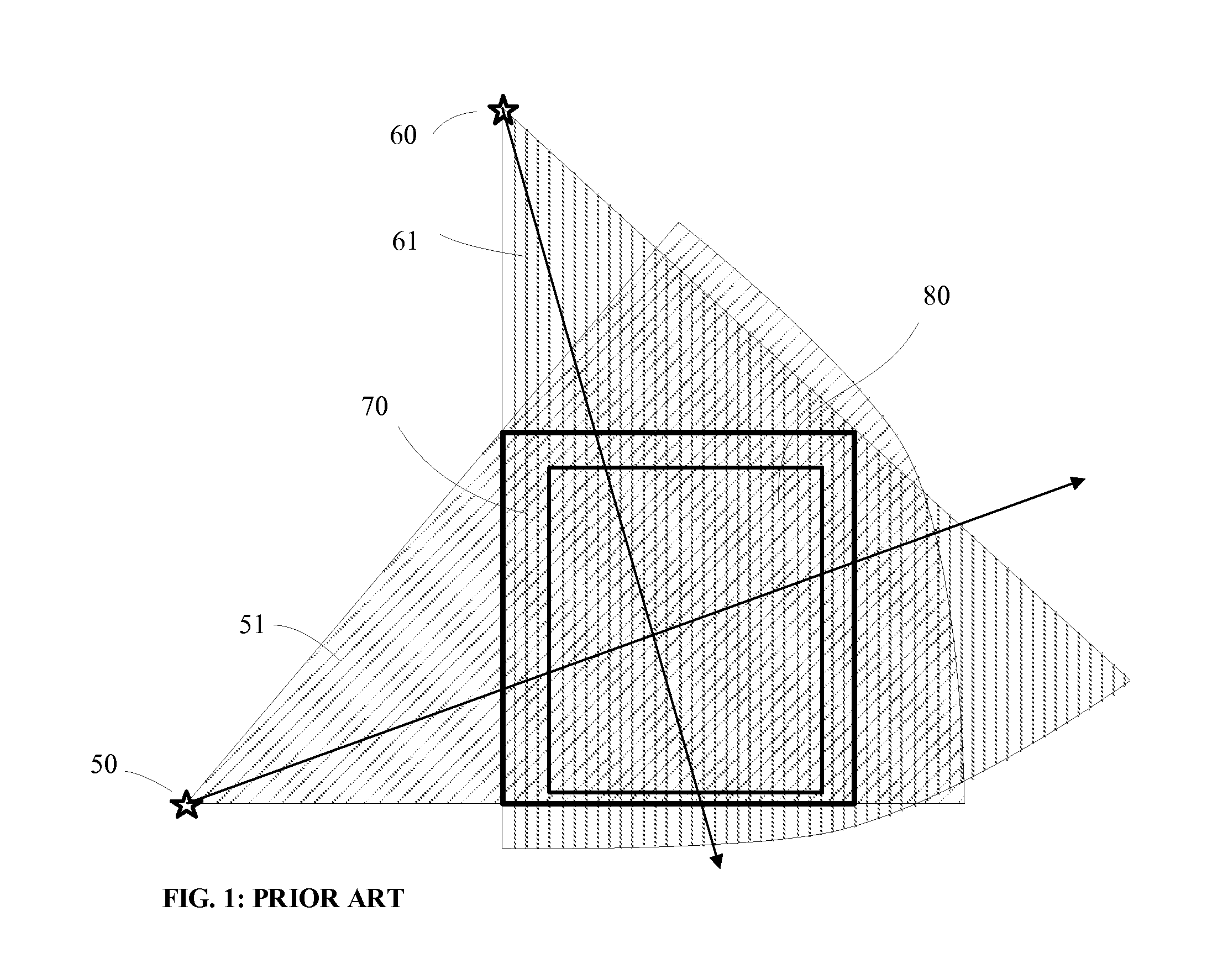
[0023]In order to understand the physics behind the novel method of this invention, reference is made to the prior art of FIG. 1 which shows a dual view system. Consider a typical requirement for pallet scanning that be able to scan pallets of 48 inches wide and 60 inches tall. Then with reference to FIG. 1, the vertical beam 61 has to pass through at least the height or 60 inches of object, whereas the horizontal beam 51 passes through the width of pallet or 48 inches of object. Since the vertical beam 61 passes through a greater length of the object, it is absorbed more than the horizontal beam, as a result the image quality suffers for ...


PUM

PropertyMeasurementUnit
heightaaaaaaaaaa
heightaaaaaaaaaa
heightaaaaaaaaaa

Abstract

This invention describes a novel beam arrangement for multiview and dual view x-ray or radiation scanning systems used for inspection of objects. The method described herein is especially suited for scanning large objects such as palletized cargo or dense objects that are longer in one dimension, for example the height being larger than the width or depth. As the size and density of the object to be scanned increase, the absorption of the x-rays by the object increases with less of x-rays reaching the detectors. Therefore, in order to receive minimal signal for acceptable image quality, the scan speed is slowed which for certain objects it might become so low that it may not be acceptable. This invention describes a novel beam arrangement that greatly speeds up the scan speed.

Description

BACKGROUND OF THE INVENTION[0001]1. Field of the Invention[0002]This invention describes a method of using x-rays or radiation to inspect an object or a parcel. This method is specially suited for large objects such as palletized cargo.[0003]2. Description of the Related Art[0004]X-ray scanning is used for inspection of baggage and cargo at airports, at ports of entries, at entry points of facilities and buildings, at check points and at various other places where security demands. The scanning of larger cargo or palletized cargo is often done by x-ray machines that have either a single or dual sources of x-ray. In a single view machine, a single source of x-ray is used, it emits a fan shaped beam which penetrates through the object being scanned and is detected by the detectors at the opposite end of the x-ray source. Often a single scan image thus obtained is not sufficient to examine the contents of the cargo, therefore a second source of x-ray is used that directs it beam at nin...

Claims


Application Information

Patent Timeline
Patent Type & Authority Applications(United States)
IPC IPC(8): G01N23/04
CPCG01V5/0058G01V5/228
Inventor SINGH, SATPAL
Owner SINGH SATPAL
Learn More