
Backlight module and electronic device using the same

a backlight module and electronic device technology, applied in the field of backlighting, can solve the problems of difficult to achieve the function of light emission, the volume and complex assembly process of the fiber backlight module play a negative role in the minimization of electronic devices, and the fiber has a relatively large diameter and is not easily curved

Inactive Publication Date: 2012-02-02
HON HAI PRECISION IND CO LTD
View PDF2 Cites 3 Cited by
  • Summary
  • Abstract
  • Description
  • Claims
  • Application Information

AI Technical Summary

Benefits of technology

[0004]In order to meet market demands, many electronic devices include the capability for light to be emitted through housings thereof. Most electronic devices include fiber backlight modules in which fibers are applied to guide light. However, the large volume and complex assembly process of the fiber backlight modules play a negative role in the minimization of the electronic devices. Furthermore, the fiber has a relatively large diameter and is not easily curved, such that the function of light emission is difficult to achieve.

Problems solved by technology

However, the large volume and complex assembly process of the fiber backlight modules play a negative role in the minimization of the electronic devices.
Furthermore, the fiber has a relatively large diameter and is not easily curved, such that the function of light emission is difficult to achieve.

Method used


Image

  • Backlight module and electronic device using the same
  • Backlight module and electronic device using the same
  • Backlight module and electronic device using the same

Examples


Embodiment Construction

[0012]The backlight module may be applied in any electronic device such as notebook computers, LCD monitors, digital cameras, and others. Here, for convenience, the backlight module described and illustrated is applied in a mobile phone.

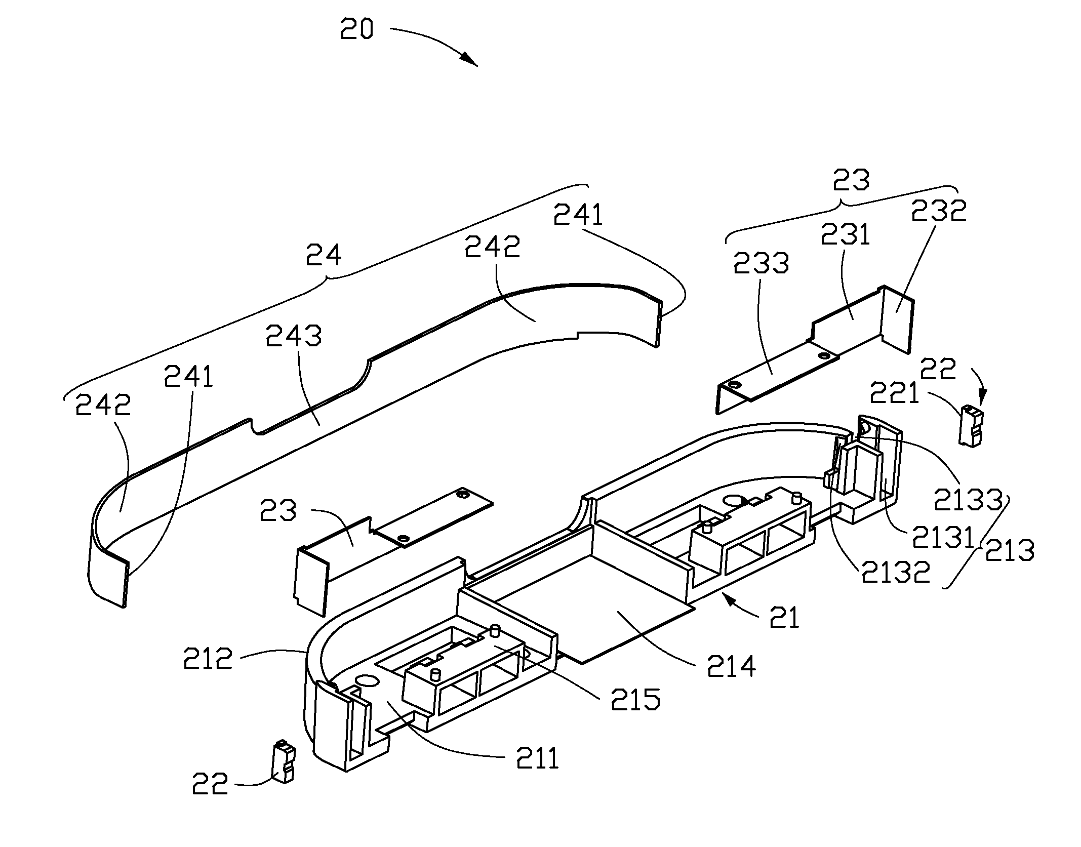
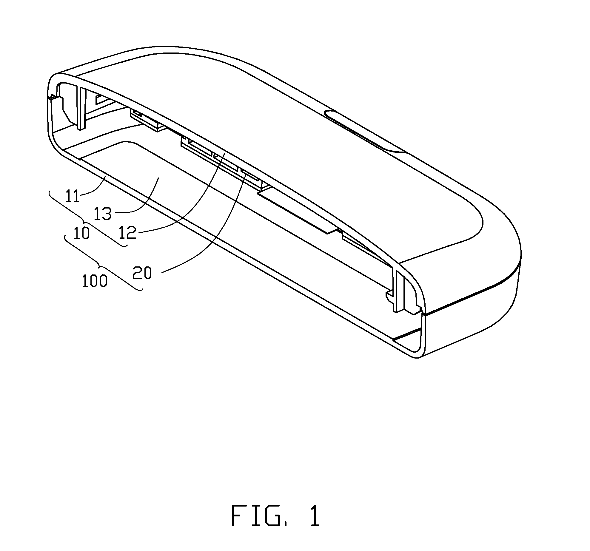
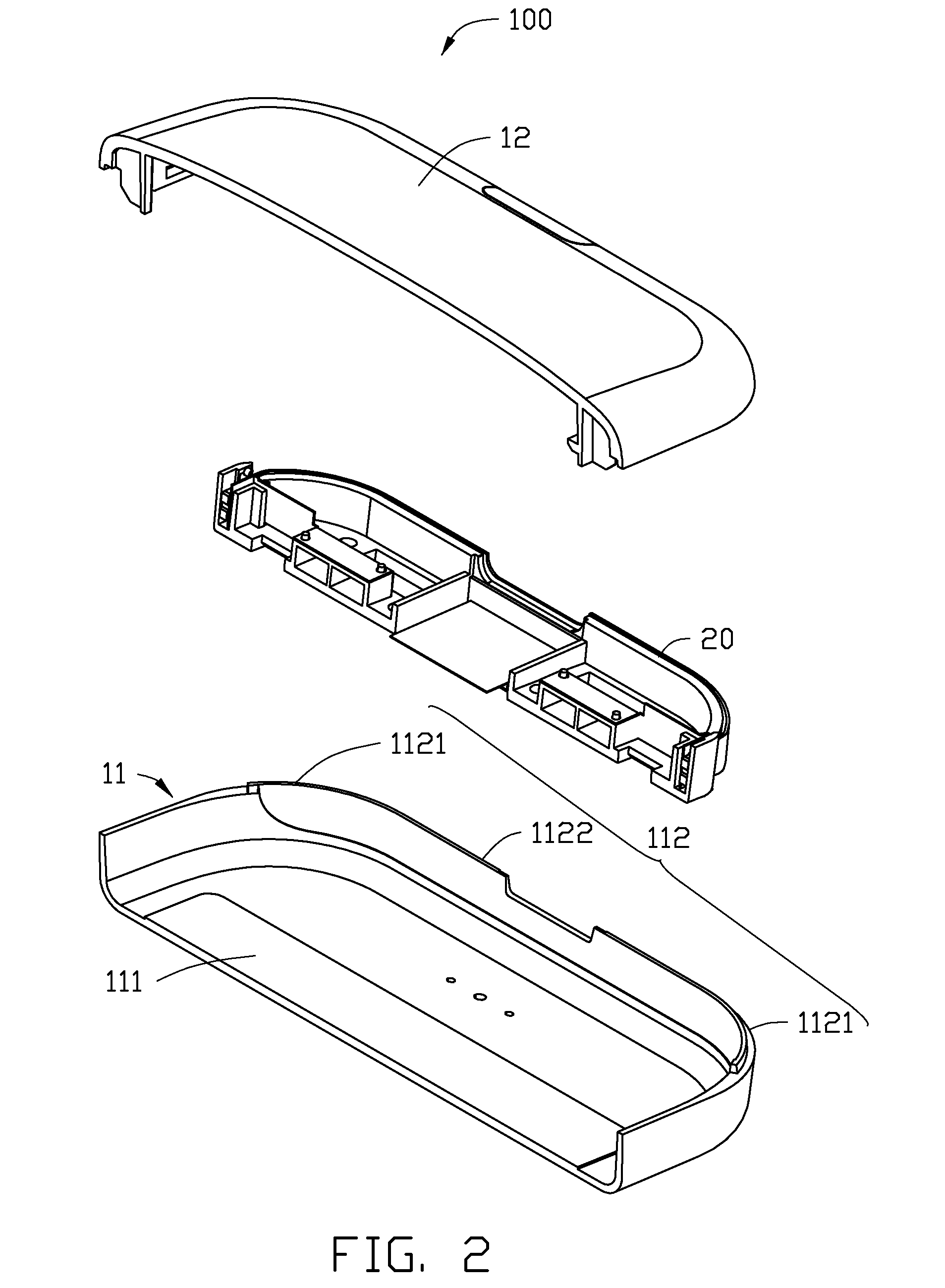
[0013]Referring to FIGS. 1 and 2, an electronic device 100 includes a housing 10 and a backlight module 20 received in the housing 10. The housing 10 includes a first cover 11 and a second cover 12 positioned on the first cover 11. The second cover 12 and the first cover 11 cooperatively define a receiving space 13 therebetween. The first and second covers 11, 12 have a plurality of latching structures (not shown) to connect the first and second covers 11, 12.

[0014]The first cover 11 includes a bottom surface 111 and a sidewall 112 substantially perpendicular to the bottom surface 111 and connects with an edge of the bottom surface 111. The sidewall 112 is of transparent material, and the sidewall 112 includes a first transparent part 1122 and two se...


PUM


Abstract

A backlight module includes a support frame, two light sources, and a light guide film. The support frame includes a support portion and a fixing portion connected to an edge of the support portion, and the support frame defines at least one receiving groove. Each light source includes a light output surface and is received in the support frame. The light guide film includes two light input surfaces at the opposite ends thereof and two light guide portions connected with the light input surfaces. The light input surfaces of the light guide film face the light output surfaces of the light sources.

Description

BACKGROUND[0001]1. Technical Field[0002]The present disclosure generally relates to backlighting, and more particularly to a backlight module applied in an electronic device.[0003]2. Description of Related Art[0004]In order to meet market demands, many electronic devices include the capability for light to be emitted through housings thereof. Most electronic devices include fiber backlight modules in which fibers are applied to guide light. However, the large volume and complex assembly process of the fiber backlight modules play a negative role in the minimization of the electronic devices. Furthermore, the fiber has a relatively large diameter and is not easily curved, such that the function of light emission is difficult to achieve.[0005]Therefore, there is room for improvement within the art.BRIEF DESCRIPTION OF THE DRAWINGS[0006]The components in the drawings are not necessarily drawn to scale, the emphasis being placed upon clearly illustrating the principles of the present di...

Claims


Application Information

Patent Timeline
IPC IPC(8): F21V7/22
CPCG02B6/0095G02B6/0086
Inventor CHIANG, CHIA-CHIN
Owner HON HAI PRECISION IND CO LTD
Learn More