
Power supply device for detecting disconnection of voltage detection lines

a technology of power supply device and voltage detection line, which is applied in the direction of electric devices, secondary cells servicing/maintenance, instruments, etc., to achieve the effects of reducing power consumption, reducing power consumption, and increasing remaining capacity

Active Publication Date: 2012-02-02
SANYO ELECTRIC CO LTD
View PDF7 Cites 6 Cited by
  • Summary
  • Abstract
  • Description
  • Claims
  • Application Information

AI Technical Summary

Benefits of technology

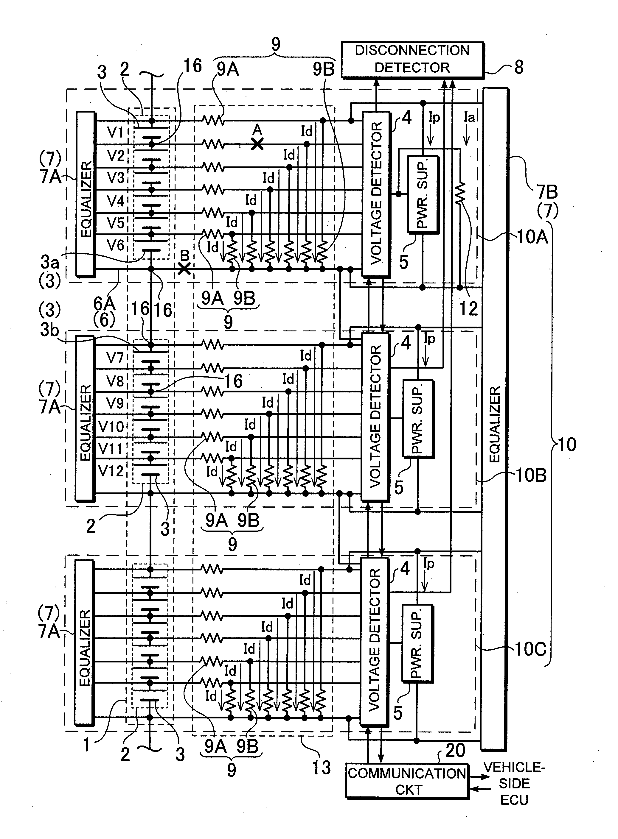
[0017]The power supply device according to the present invention can further include an equalizing circuit 7 that achieves the cell balance between the battery cells 3, which constitute the battery blocks 2, and corrects the unbalance between the battery blocks 2, which constitute the battery pack 1. According to the thus-constructed power supply device, since the device includes equalizing circuit, it is possible to prevent that with elapsed time the voltages of the battery cells get unbalanced which constitute a battery block, and that with elapsed time the voltages and remaining capacities of the battery blocks get unbalanced which constitute a battery pack block.
[0018]In the power supply device according to the present invention, the equalizing circuit 7 can adjust the at least one of the battery blocks 2, which has higher power consumption, to a higher remaining capacity than the remaining capacity of other of the battery blocks 2, which has lower power consumption. According to the thus-constructed power supply device, since a battery block with higher consumption current is adjusted to a higher remaining capacity, it is possible to reduce the number of adjustment times for equalization.

Problems solved by technology

The reason is that the unbalance resistor controls the consumption current of the at least one of the battery blocks so that currents flow in all of the voltage detection lines.

Method used


Image

  • Power supply device for detecting disconnection of voltage detection lines
  • Power supply device for detecting disconnection of voltage detection lines
  • Power supply device for detecting disconnection of voltage detection lines

Examples


Embodiment Construction

)

[0031]The following description will describe embodiments according to the present invention with reference to the drawings.

[0032]A vehicle power supply device shown in FIG. 4 is installed in a hybrid car or electric vehicle, and is used to supply electric power to a motor for driving the vehicle. However, of the power supply device according to the present invention is not limited to be used as a power supply device for supplying electric power to an electric motor for driving a vehicle. The power supply device includes a number of battery cells, which are serially connected to each other for increasing output voltage, and can be used in any use where a large amount of output is required.

[0033]The power supply device includes a plurality of battery units 10. Each of the battery units 10 includes a battery block 2, a voltage detecting circuit 4, a power supply circuit 5, and a disconnection detecting circuit 8. The battery block 2 includes a plurality of battery cells 3 that are se...


PUM

PropertyMeasurementUnit
currentaaaaaaaaaa
currentaaaaaaaaaa
consumption currentsaaaaaaaaaa

Abstract

A power supply device includes battery units 10. Each unit 10 includes a battery block 2, a voltage detector 4, a power supply circuit 5, and a disconnection detector 8. The block 2 includes serially-connected battery cells 3. The voltage detector 4 detects the cell 3 voltages through voltage detection lines 6. The power supply circuit 5 supplies power from the block 2 to the voltage detector 4. The voltage detector 4 is powered by electric power from the block 2. The disconnection detector 8 detects disconnection of the lines 6 based on the detected cell 3 voltages. An unbalance resistor 12 is connected to one of the blocks 2 to increase power consumption of this block 2. Thus, a current flows in the line 6 that is connected to a node16 between this block 2 and an adjacent block connected next to this block 2.

Description

BACKGROUND OF THE INVENTION[0001]1. Field of the Invention[0002]The present invention relates to a power supply device including a battery pack including a number of battery cells serially connected to each other, and in particular to a power supply device detecting voltages of the battery cells and safely charging / discharging the battery cells.[0003]2. Description of the Related Art[0004]A battery pack required to provide a large amount of output includes a number of battery cells serially connected to each other for increasing output voltage. Since the battery cells in this battery pack are serially connected to each other, the charging and discharging current values of all of the battery cells are same as each other. However, in the battery pack including a number of battery cells serially connected to each other, since the battery cells cannot have completely the same characteristics, the unbalance between their electrical characteristics may bring a particular battery cell to b...

Claims


Application Information

Patent Timeline
Patent Type & Authority Applications(United States)
IPC IPC(8): G01N27/416H01M10/46B60L3/00H02J7/00H02J7/02
CPCH01M10/441H02J7/0018H01M10/482Y02E60/10H02H7/18G01R31/36
Inventor FURUKAWA, KIMIHIKO
Owner SANYO ELECTRIC CO LTD
Learn More