
Photovoltaic solar cell overlay

Inactive Publication Date: 2012-02-02
RENESSELAER POLYTECHNIC INST
View PDF1 Cites 2 Cited by
  • Summary
  • Abstract
  • Description
  • Claims
  • Application Information

AI Technical Summary

Benefits of technology

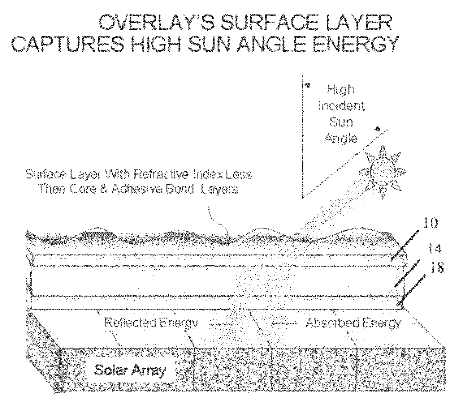
[0017]In accordance with the present invention, there is provided an add-on device for photovoltaic solar cells to capture solar energy normally unavailable at high incident sun angles. The device does not require precise positioning of optical elements above the array, sun sensors, or solar array panel vectoring mechanisms. The concept described herein is neither complex nor costly and thus advances the state-of-the-art for commercial and residential applications.
[0019]In most simplistic form, the device is comprised of a transparent solar cell array overlay imbued with specific optical characteristics and / or surface contours. The solar cell array overlay may be comprised of any transparent material such as glass, optical grade acrylics, polymers, or any other suitable high-transmittance media with refractive or diffractive indices or other optical characteristics suitable for re-directing the incident sun energy towards the normal to the plane of the device. The overlays also may be constructed from or contain gas, fluid, or plastic materials and be capable of adjusting contours or optical characteristics using sun angle, thermal or sensed solar power output as control devices. Generally, the solar array overlays will consist of two types; a fixed configuration type produced from fixed-form materials such as optical-grade glass or acrylics, and a variable configuration or variable optics type which may employ thermally-sensitive gas or fluids contained in optical-grade acrylic film. The function of either overlay type is to re-direct impinging sun energy so as to improve solar cell power yields at higher sun angles.

Problems solved by technology

The current state-of-the-art for solar power installations relies on costly and complex sun-tracking systems.
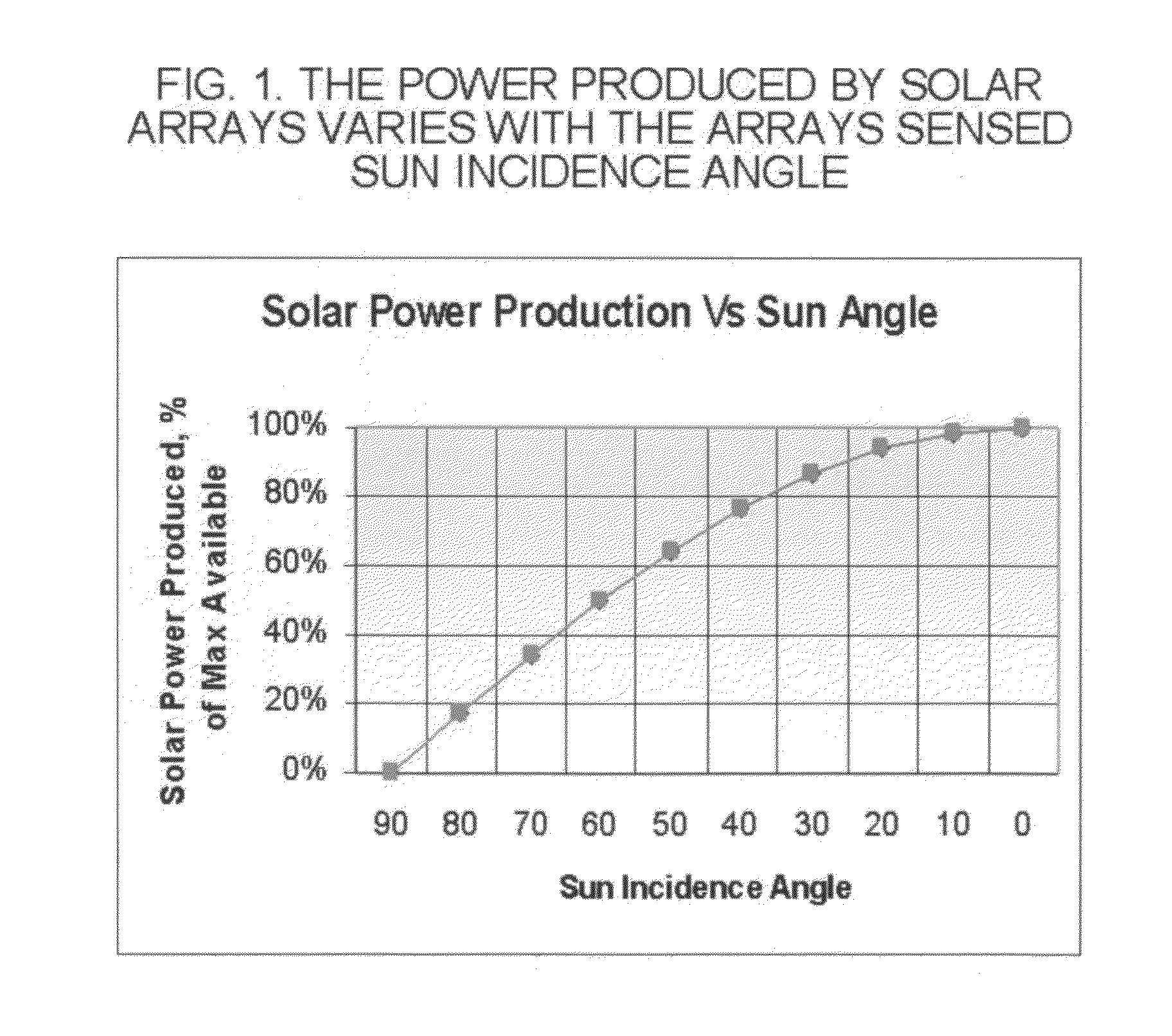
In fact, the power produced by photovoltaic solar cells is limited to the cosine of the cell's incident angle to the sun.
Although sun-tracking equipment installed on solar arrays can increase viable output by up to 100%, it is not practical for many commercial and residential solar power applications to install or retro-fit such vectoring systems.
The cost and complexity of such systems would be prohibitive.
Even so, fixed mount installations can lose as much as half the power available due to the fact that solar cell power output decays rapidly as the incident sun angle the increases.
These solar power applications incorporate complex systems requiring sun-tracking sensors linked to attitude control servo mechanisms.
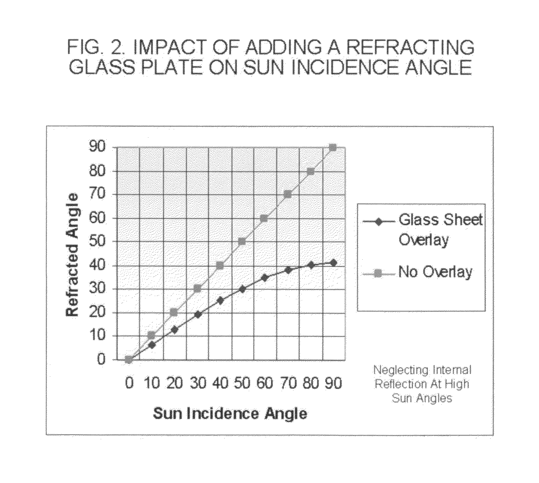
Although solar cell modules usually are protected by a thin sheet of glass on sun facing side, the glass does not improve performance of the array at high sun angles.
This device cannot maintain optimum sun angles on the solar cells.
Moreover, the Rensselaer device adds considerable expense and complexity, requiring optical elements and additional support structures mounted above the array in a precise attitude and position.
The sun-tracking sensors and solar panel attitude control mechanisms currently in use are not practical for most commercial and residential applications because of their cost and complexity.

Method used


Image

  • Photovoltaic solar cell overlay
  • Photovoltaic solar cell overlay
  • Photovoltaic solar cell overlay

Examples


Embodiment Construction

[0033]The purpose of the solar array overlay device is to capture solar energy normally unavailable to a fixed-position solar array at higher incident sun angles. Power produced by un-vectored solar power applications drops off sharply in the morning and afternoon due to the higher sun incident angles encountered. The device described herein utilizes one or more layers of transparent media joined in-plane to the solar array and imbued with specific optical characteristics capable of bending incident light towards the normal to the plane of the attached device. The overlays are comprised of light-bending optical materials such as dense glass, optical grade acrylics, polymers, or any other suitable high-transmittance media with adequate refractive, diffractive, or reflective characteristics. For typical terrestrial applications, the device layers are bonded to one-another and to the solar array without an air gap at the overlay-to-solar array interface. Any suitable bonding adhesive w...


PUM


Abstract

This abstract describes a simple, low-cost device to improve power yields provided by fixed solar panel installations without the need to precisely position optical elements above the panel or add solar tracking and array positioning systems. The device utilizes one or more layers of optically refractive and / or diffractive materials imbued with specific contours and / or optical characteristics. The device is bonded directly to the solar array's sun-facing surface either as the array is manufactured, or retro-fitted to the array after installation. The device and bond interfaces may be comprised of any suitable optically high-transmittance material with refractive indices sufficiently higher than that of air. Additional gains in solar array power yields are made possible by the use of transparent, variable-contoured overlays or fluid-filled polymeric film overlays with modifiable optical characteristics which adapt to sun angle.

Description

RELATED APPLICATIONS[0001]The present application is related to U.S. Pat. No. 452,496, issued Jul. 3, 2008, for DESIGN AND FABRICATION OF A LOCAL CONCENTRATOR SYSTEM, by Dutta, Partha, included by reference herein.[0002]Assigned to Rensselaer PolytechnicFIELD OF THE INVENTION[0003]The present invention relates a device for improving solar array power yields, and more particularly, for capturing solar energy at incident sun angles normally unavailable to fixed-position installations.BACKGROUND OF THE INVENTION[0004]The current state-of-the-art for solar power installations relies on costly and complex sun-tracking systems. These solar power systems constantly monitor the movement of the sun to maintain an optimum angle to the incident sun energy. In fact, the power produced by photovoltaic solar cells is limited to the cosine of the cell's incident angle to the sun. For example, when the sun's incident angle falls off from 0 degrees directly overhead to −60 degrees in the afternoon, ...

Claims


Application Information

Patent Timeline
IPC IPC(8): H01L31/052
CPCH01L31/0543Y02E10/52
Inventor EVANBAR, MICHAEL STEPHEN
Owner RENESSELAER POLYTECHNIC INST
Learn More