Switching-device remaining lifetime diagnosis method and apparatus

a technology of switching devices and diagnostic methods, applied in the direction of instruments, testing/monitoring control systems, process and machine control, etc., can solve the problems of deterioration in such a switching device and the expiration of the remaining lifetime thereof, and achieve the and accurate estimation of the remaining lifetime of the switching device.

Active Publication Date: 2012-01-26
MITSUBISHI ELECTRIC CORP
View PDF5 Cites 18 Cited by
  • Summary
  • Abstract
  • Description
  • Claims
  • Application Information

AI Technical Summary

Benefits of technology

[0033]In a switching-device remaining lifetime diagnosis method according to the present invention, as status amount history data, there are accumulated status amounts related to a deterioration status of a switching device, estimated based on measurement data obtained through measurement of performance characteristics of the switching device; based on the accumulated status amount history data, there are created at least one of system data in which the status amounts are arranged with the abscissa of at least part of an elapsed time during an operation period of the switching device, system data in which the status amounts are arranged with the abscissa of the number of operations of the switching device during the at least part of an elapsed time, system data in which the status amounts are arranged with the abscissa of an inoperative time of the switching device during the at least part of an elapsed time, and system data in which the status amounts are arranged with the abscissa of an accumulated operation time of the switching device during the at least part of an elapsed time; based on the created system data pieces, the remaining lifetime of the switching device is estimated. As a result, by separating deterioration factors caused in a switching device, the remaining lifetime of the switching device can accurately be estimated.
[0034]Moreover, in a switching-device remaining lifetime diagnosis method according to the present invention, as status amount history data, there are accumulated status amounts related to a deterioration status of a switching device, estimated based on measurement data obtained through measurement of performance characteristics of the switching device; based on the accumulated status amount history data, there is calculated the variance value of the status amounts every predetermined number of measurements, and then there are created at least one of system data in which the variance values are arranged with the abscissa of at least part of an elapsed time during an operation period of the switching device, system data in which the variance values are arranged with the abscissa of the number of operations of the switching device during the at least part of an elapsed time, system data in which the variance values are arranged with the abscissa of an inoperative time of the switching device during the at least part of an elapsed time, and system data in which the variance values are arranged with the abscissa of an accumulated operation time of the switching device during the at least part of an elapsed time; based on the created system data pieces, the remaining lifetime of the switching device is estimated. As a result, it is made possible to estimate the remaining lifetime of the switching device even in the case of a deterioration factor that does not indicate any deterioration tendency in system data in which status amounts are arranged with the abscissa of an elapsed time, the number of operations, an inoperative time, or an accumulated time.
[0035]Still moreover, in a switching-device remaining lifetime diagnosis method according to the present invention, as status amount history data, there are accumulated status amounts related to a deterioration status of a switching device, estimated based on measurement data obtained through measurement of performance characteristics of the switching device; the status amounts in the accumulated status amount history data are transformed by use of a predetermined transformation function into predetermined status amounts, and then there are created at least one of system data in which the predetermined status amounts are arranged with the abscissa of at least part of an elapsed time during an operation period of the switching device, system data in which the predetermined status amounts are arranged with the abscissa of the number of operations of the switching device during the at least part of an elapsed time, system data in which the predetermined status amounts are arranged with the abscissa of an inoperative time of the switching device during the at least part of an elapsed time, and system data in which the predetermined status amounts are arranged with the abscissa of an accumulated operation time of the switching device during the at least part of an elapsed time; based on the created system data pieces, the remaining lifetime of the switching device is estimated. As a result, the remaining lifetime of the switching device can more accurately be estimated.
[0036]Moreover, in a switching-device remaining lifetime diagnosis method according to the present invention, as status amount history data, there are accumulated status amounts related to a deterioration status of a switching device, estimated based on measurement data obtained through measurement of performance characteristics of the switching device; based on the accumulated status amount history data, there are created at least one of system data in which the status amounts are arranged with the abscissa of a total elapsed time during an operation period of the switching device, system data in which the status amounts are arranged with the abscissa of the number of operations of the switching device during the total elapsed time, system data in which the status amounts are arranged with the abscissa of an inoperative time of the switching device during the total elapsed time, and system data in which the status amounts are arranged with the abscissa of an accumulated operation time of the switching device during the total elapsed time, and, at the same time, there are created at least one of system data in which the status amounts are arranged with the abscissa of an elapsed time during a period after the time point when a predetermined period has elapsed from a time point when the switching device had initially started to operate, system data in which the status amounts are arranged with the abscissa of the number of operations of the switching device in an elapsed time during a period after the time point when the predetermined period has elapsed, system data in which the status amounts are arranged with the abscissa of an inoperative time of the switc

Problems solved by technology

The deterioration in such a switching device develops due to contributing factors such as an elapsed time from a time point when the switching device has initially started its operation, the number of operations, the time

Method used


Image

  • Switching-device remaining lifetime diagnosis method and apparatus
  • Switching-device remaining lifetime diagnosis method and apparatus
  • Switching-device remaining lifetime diagnosis method and apparatus

Examples


embodiment 1

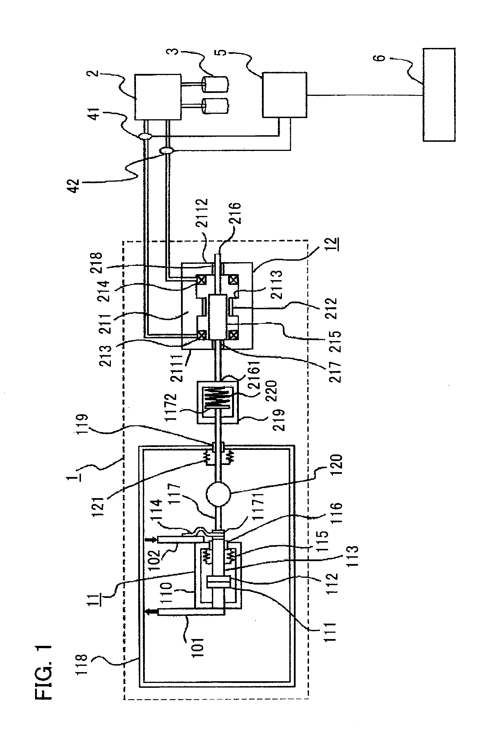
[0047]Hereinafter, a switching-device remaining lifetime diagnosis apparatus according to Embodiment 1 of the present invention will be explained in detail. FIG. 1 is a configuration diagram illustrating a switching-device remaining lifetime diagnosis apparatus according to Embodiment 1 of the present invention. A switching-device remaining lifetime diagnosis method according to Embodiment 1 of the present invention is implemented by a switching-device remaining lifetime diagnosis apparatus according to Embodiment 1, and will clearly be explained with reference to FIG. 1.

[0048]In FIG. 1, a switching device 1 is provided with a vacuum valve 11 that opens or closes a main circuit, which is an electric circuit configured with main circuit conductors 101 and 102, and an electromagnetic actuator 12, which is a driving mechanism for driving the vacuum valve 11.

[0049]The vacuum valve 11 is provided with a case 110 that is kept approximately vacuum; inside the case 110, there are contained ...

case 1

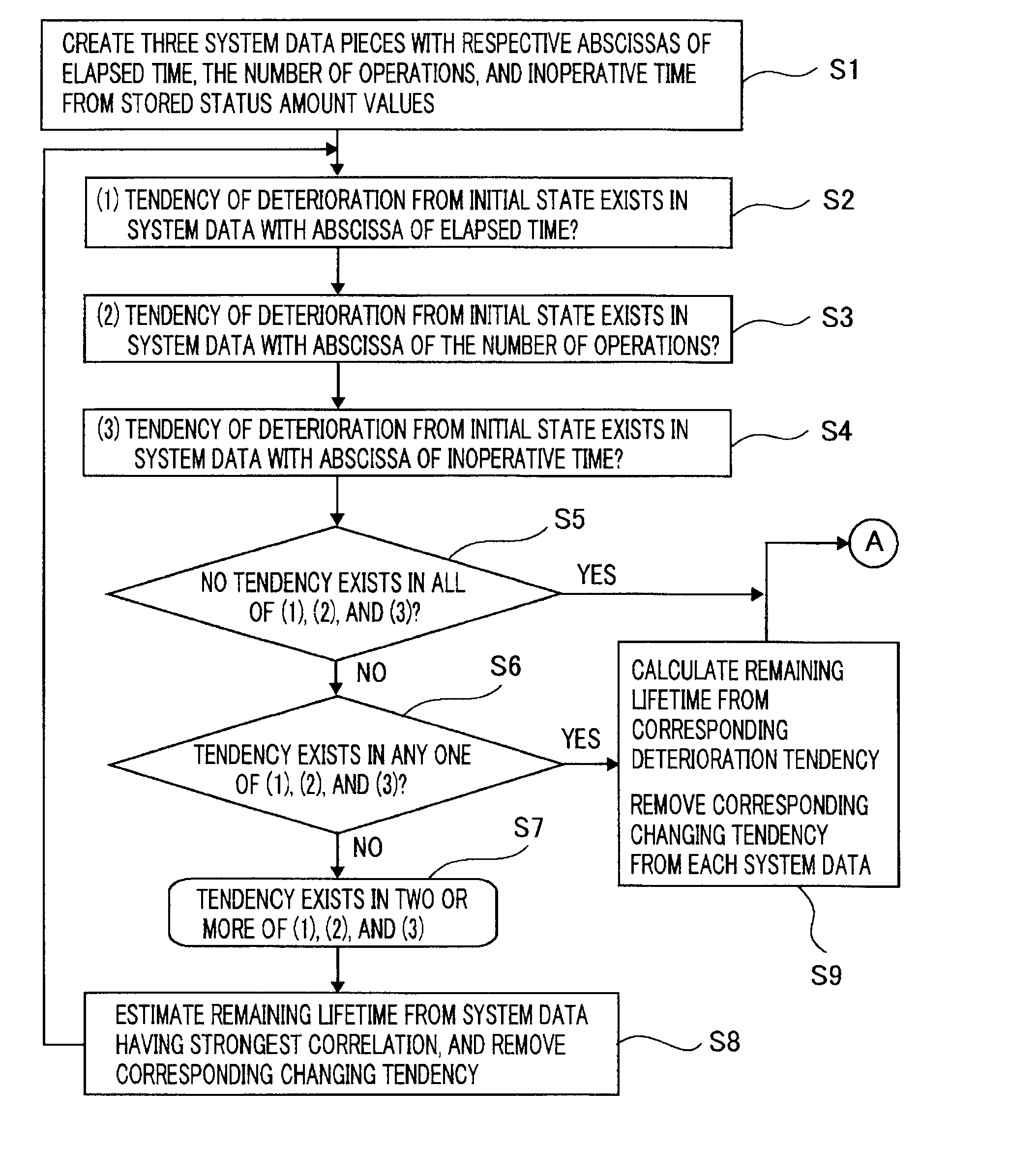
[0102]Here, at first, as Case 1, explanation will be made assuming a case where it is determined in the step S2 that the frictional force F in the first system data has a deterioration tendency, it is determined in the step S3 that the frictional force F in the second system data has a deterioration tendency, and it is determined in the step S4 that the frictional force F in the third system data has a deterioration tendency. In addition, in Case 1, it is assumed that the first system data has the strongest correlation.

[0103]In Case 1, the result of the determination in the step S5 becomes “NO”; then, the step S5 is followed by the step S6. In the step S6, it is determined whether or not in only one of the results of the determinations implemented in the steps S1, S2, and S3, there is recognized a tendency in which the frictional force F is deteriorated; thus, the result becomes “NO”, and then the step S6 is followed by the step S7. In the step S7, in the case where it is determined...

case 2

[0125]Next, as Case 2, there will be explained a case where in two of the steps S2, S3, and S4, it is determined that there exists a deterioration tendency of the frictional force F in the system data.

[0126]In Case 2, there exists a deterioration tendency of the frictional force F in two of the three system data pieces; as is the case with Case 1, the flow of the flowchart advances from the step S1 to the step S8 by way of the process including the steps S2, S3, S4, S5, S6, and S7.

[0127]In the step S8, for the system data that has the strongest correlation among the two system data pieces, an optimum regression line is obtained; then, from this regression line, there is calculated an elapsed time, the number of operations, or an inoperative time in which the frictional force F reaches the limit value with which the switching device 1 cannot satisfy predetermined performance any more. Provided the first system data has the strongest correlation, based on the optimum regression line R...


PUM


Abstract

There are provided a switching-device remaining lifetime diagnosis method and a switching-device remaining lifetime diagnosis apparatus, wherein as status amount history data, there are accumulated status amounts related to a deterioration status of a switching device, estimated based on measurement data obtained through measurement of performance characteristics of the switching device; based on the accumulated status amount history data, there are created a plurality of system data pieces in which the status amounts are arranged with the respective abscissas of an elapsed time during an operation period of the switching device, the number of operations of the switching device, an inoperative time of the switching device, and an accumulated operation time of the switching device; based on the created system data pieces, the remaining lifetime of the switching device is estimated.

Description

TECHNICAL FIELD[0001]The present invention relates to a switching-device remaining lifetime diagnosis method in which the remaining lifetime of a switching device is diagnosed based on the performance characteristics of the switching device and to a remaining lifetime diagnosis apparatus utilizing the remaining lifetime diagnosis method.BACKGROUND ART[0002]In general, a switching device such as an electric power switching device (simply referred to as a switching device, hereinafter) is provided with a fixed contact, a movable contact that is provided in such a way as to face the fixed contact, and a driving mechanism that drives the movable contact in such a way that the movable contact comes in contact with the fixed contact or is separated from the fixed contact. The deterioration in such a switching device develops due to contributing factors such as an elapsed time from a time point when the switching device has initially started its operation, the number of operations, the tim...

Claims


Application Information

Patent Timeline
IPC IPC(8): G01B3/00G01M99/00
CPCG01R31/3274G05B23/0283H01H2071/044H01H33/6662H01H3/001G01M99/00G05B23/02H02B13/00
Inventor MARUYAMA, AKIHIKOMARUYAMA, YUKOHORINOUCHI, KATSUHIKO
Owner MITSUBISHI ELECTRIC CORP
Why Eureka
Try Eureka