
Warming therapy device including heated mattress assembly

a mattress and heating technology, applied in the field of heating devices for medical patients, can solve the problems of often leaving artifacts on the x-ray image, not being transparent to x-rays, and affecting the care of patients disposed on the mattress,

Inactive Publication Date: 2012-01-26
DRAEGER MEDICAL SYST INC
View PDF3 Cites 23 Cited by
  • Summary
  • Abstract
  • Description
  • Claims
  • Application Information

AI Technical Summary

Benefits of technology

[0015]An exemplary embodiment of the present invention also comprises a control system including at least one heating element, a system controller coupled to the at least one heating element, an...

Problems solved by technology

The metal plate design provides some degree of uniform temperature distribution across the surface of the mattress, however, it is also non-transparent to X-rays.
So, an X-ray cassette can only be placed over the mattress support containing the metal plate, which may interfere with the care of the patient disposed on the mattress.
However, such structures often leaves artifacts on the X-ray image due to non-X-ray transparent temperature control sensors, buses and connecting wires disposed in the area around the carbon fiber layer.
The above-described metal plate design is also not usable in ‘oxygen rich’ environments because it consumes more power than is acceptable under current International Electrotechnical Commission (EC) guidelines.
Existing carbon fiber beaters are similarly unusable in ‘oxygen rich’ environments because of the above-described IEC guidelines.
Although the above-referenced patents described temperature sensors for controlling heating, such sensors do not operate to maintain power consumption levels below IEC guidelines for oxygen rich environments.
In particular, conventional warming therapy devices are unable to maintain a desired temperature distribution at the interface between the mattress and the patient.
In particular, conventional warming therapy devices are unable to achieve and maintain different temperatures depending on the presence or absence of oxygen in the surrounding environment.

Method used


Image

  • Warming therapy device including heated mattress assembly
  • Warming therapy device including heated mattress assembly
  • Warming therapy device including heated mattress assembly

Examples


Embodiment Construction

[0030]The present invention relates to a warming therapy device (e.g., incubator, warmer, etc.) including a heated mattress tray assembly. In particular, the warming therapy device includes a resistive or radiolucent heater disposed within a mattress tray assembly for providing heating of a patient disposed on the mattress tray assembly in one embodiment. In another embodiment, the warming therapy device includes a segmented carbon fiber heater coupled to an oxygen control device and disposed within a mattress tray assembly for providing heating of a patient situated on the mattress tray assembly.

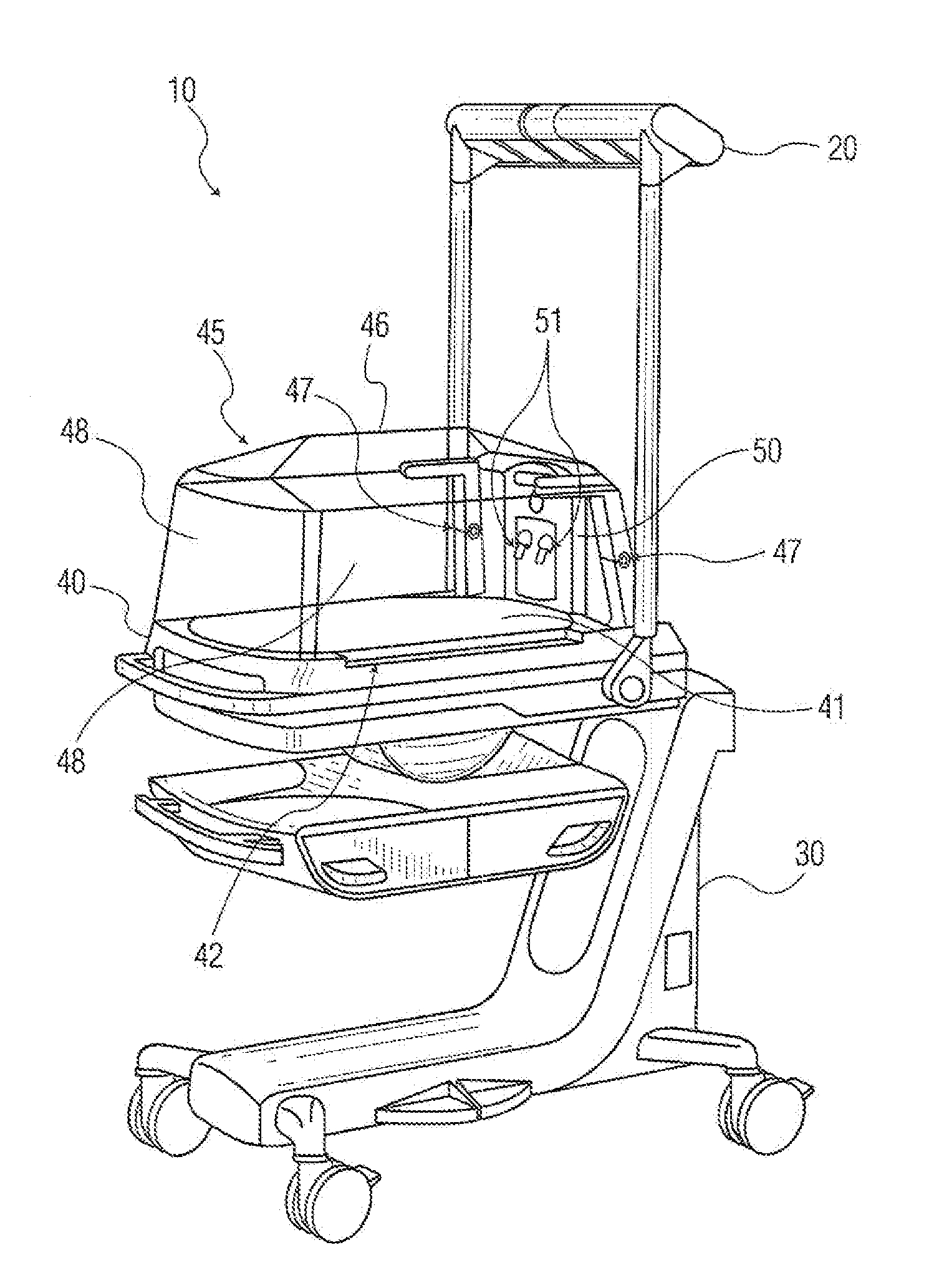
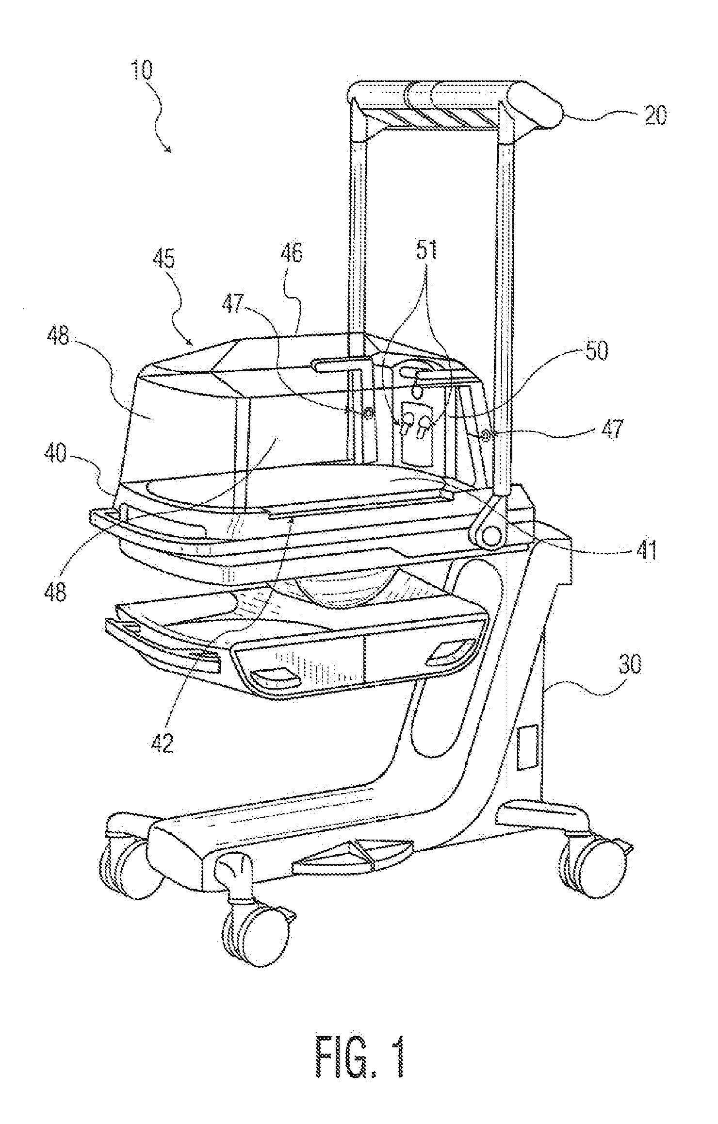
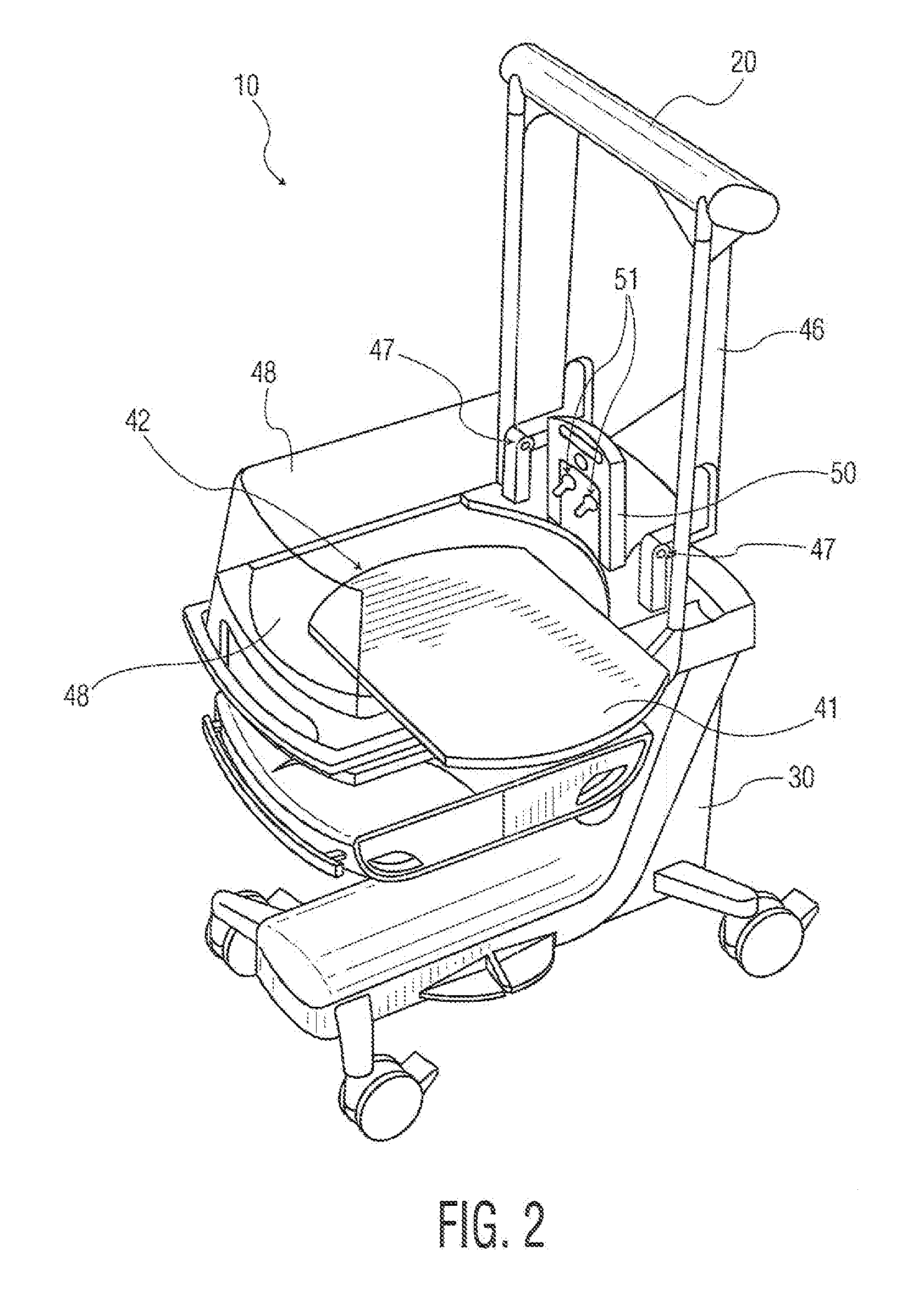
[0031]FIGS. 1 and 2 show a warming therapy device 10 according to a first exemplary embodiment of the present invention. The warming therapy device 10 includes a radiant heater head 20, and a patient support assembly 30 including a mattress tray assembly 40. The mattress tray assembly 40 may include a hood 45 which has a top portion 44 which pivots about one or more axes 47. The hood 45 may...


PUM


Abstract

An apparatus and method for performing warming therapy is described. In one exemplary embodiment, the apparatus includes a patient support assembly and at least one heating element coupled to the patient support assembly, formed of a plurality of heating cells. In another exemplary embodiment, the heating element is formed of a plurality of separate heating segments which may be Individually controlled. In yet another exemplary embodiment, the heating element is coupled to at least one oxygen sensor and a control system for controlling the power applied to the heating element based on the oxygen level measured by the oxygen sensor. The heating element may be made of materials which are X-ray transparent, so that a patient disposed on a heated mattress will not need to be moved from the mattress to have effective X-ray diagnostics performed.

Description

CROSS REFERENCE TO RELATED APPLICATIONS[0001]This application claims priority to U.S. Provisional Application Ser. No. 61 / 161,184, filed Mar. 18, 2009, and U.S. Provisional Application Ser. No. 61 / 170,173, filed Apr. 17, 2009, the entire contents of both of which are hereby incorporated by reference, as if fully set forth herein.FIELD OF THE INVENTION[0002]This present invention relates generally to a method and apparatus for performing warming therapy on medical patients. More particularly, the present invention relates to a method and apparatus for heating a mattress in a warming therapy device, wherein the heating apparatus is X-ray transparent, and wherein the heating system includes an oxygen monitoring system for providing control feedback to control the power applied to the heating apparatus.BACKGROUND OF THE INVENTION[0003]Conventional warming therapy devices achieve patient warming through the use of air pumps and convective and radiant heaters. Some existing devices also u...

Claims


Application Information

Patent Timeline
IPC IPC(8): A61F7/08H05B3/02A61B6/04A61F7/00A47C21/04
CPCA61B6/045A61F7/007A61G11/00A61G2203/46A61N5/0621A61N2005/0659A61G11/005A61G2210/90A61G2210/50
Inventor KHODAK, ANDREIMETT, FRANKSABOTA, PETER D.PATEL, KANTIPHILLIPS, MARK A.
Owner DRAEGER MEDICAL SYST INC
Learn More