Aerated composter and waste collection bin

a composter and bin technology, applied in bioreactors/fermenters, specific use bioreactors, products, etc., can solve the problems of releasing liquid, affecting the efficiency of air exchange, and affecting the quality of composting, so as to minimize or eliminate any leakage from the unit, efficient and thorough air exchange

Inactive Publication Date: 2012-01-26
SOUTH PROVIDENCE DEV
View PDF16 Cites 17 Cited by
  • Summary
  • Abstract
  • Description
  • Claims
  • Application Information

AI Technical Summary

Benefits of technology

[0011]The compost bin of the present invention includes a container that has a perforated, dual ventilation tube design that penetrates into the center of the bin, and thus the composting materials, and allows for more thorough air circulation, and aeration of composting materials. The container's ventilation is placed strategically to minimize or eliminate any leakage from the unit while still allowing efficient and thorough air exchange. Whereas most compost bins contain perforations on the lower part of the shell, and thus lack control of leakage; this tubular design ventilated materials from top to bottom, and eliminates the need for shell ventilation holes at the bottom half of the bin; this design allows for complete containment of liquids and controlled liquids release via the spigot at the base of the bin.
[0012]The perforated vertical ventilation tube attached to dual lateral vent tubes allows for continuous air flow and more frequent air exchange and thus oxygenation of composting materials; air exchange and oxygenation of composting materials accelerates the composting process and minimizes odor events associated with anaerobic conditions and stagnant air. The perforated vertical tubing is sized to allow for efficient air exchange while mitigating material's clogging the vent system. The lateral tubes are vented on the underside of the tubes; this also allows for efficient air exchange while preventing materials from entering the perforations and clogging the ventilation. The dual vent system allows for continuous flow of air through the vent system; as opposed to a single vent that would compete with air flow entering and exiting the vent system. With an option for a powered fan attached to the upper vertical tube, air exchange and removal of excess condensation are further enhanced and composting is further accelerated as a result. Power sources for the fan may be battery or a solar photovaltaic cell.
[0013]The vertical ventilation also allows for liquids to filter through perforations and via gravity action collect in the bottom of the compost bin. A drain with a spigot at the base of the compost bin is fastened via an inverted half-pipe to the floor of the bin and to the flange of the vertical tube. By attaching the drain system to the flange of the perforated ventilation tube, this allows for efficient control and removal of liquids from the compost bin. These liquids are valuable and may be collected and converted into a compost tea; which may be utilized as a liquids fertilizer and foliar spray.
[0014]This method to remove liquids and excess condensation from the compost bin (via enhanced air circulation through the vent tubes and the drain system) also allows for overall weight reduction of materials, which may result in cost reductions associated with tipping the bins during servicing at a commercial site.
[0015]These bins are designed to be utilized in at a commercial site as well as a residential dwelling. These compost bins are tippable and may be integrated into a waste and recycling management system. These compost bins contain wheels that allow for ease of movement and placement. The vertical upright design results in a small footprint of the unit.
[0016]These bins are designed for extending collection and storage for Source Separated Organics while minimizing odors associated with waste food materials. These compost bins are intended to be utilized at an institution such as a school or hospital, a commercial site, such as a restaurant or university dining hall or a residential dwelling. These compost bins are also designed to allow for accelerated and efficient composting and thus the composting process may be initiated at any time during the collection process. By allowing the option to initiate the composting process at the collection site, material's collection time is lengthened and odor events are minimized and or eliminated. Longer collection windows translates into less frequent tipping and servicing and lower costs associated with waste and recycling management.

Problems solved by technology

In closely packed commercial or residential settings, however, composting can become problematical.
Specifically, the matter that is decaying into compost can emanate offensive odors.
Furthermore, liquid is released from the decomposition of material composting which can make a mess.

Method used


Image

  • Aerated composter and waste collection bin
  • Aerated composter and waste collection bin
  • Aerated composter and waste collection bin

Examples


embodiment 100

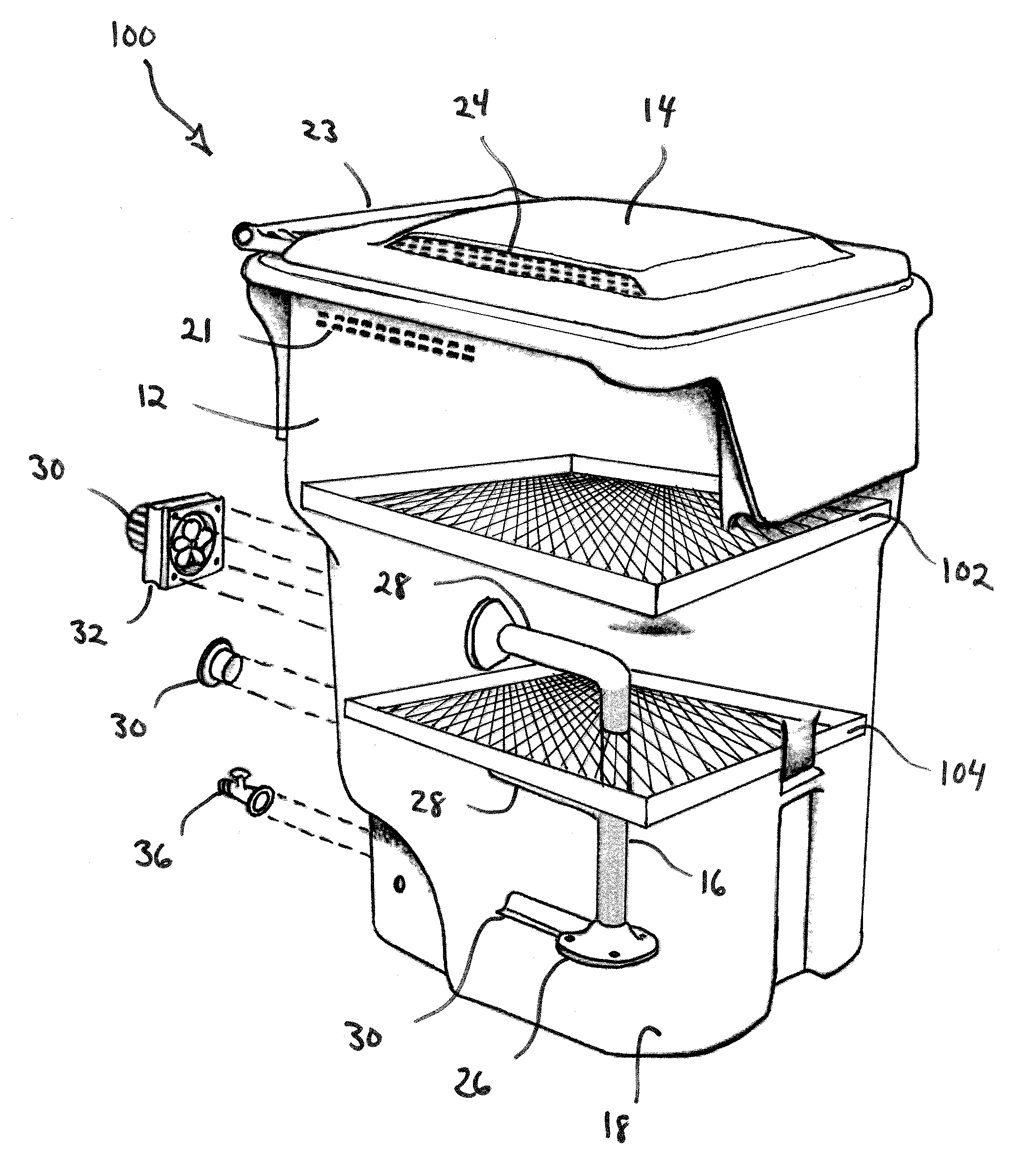
[0035]Referring now to FIG. 3, a first alternative embodiment of the compost bin 10 is shown generally at 100. The first alternative embodiment 100 includes an optional first shelf 102 located above the perforated vent tube 16. The first shelf 102 includes a number of openings that function like a grate. That is, the composting material sit atop the first shelf and as the material decays and composts, it falls through the openings to the bottoms 18 below. The large particles of composting material remain above the first shelf 102 until it sufficiently decays enough to fall through the openings of the first shelf.

[0036]An optional second shelf 104 may be spaced below the first shelf 102. The second shelf 104 includes a number of openings that are smaller than the openings on the first shelf 102. The second shelf 104 functions in the same manner as the first shelf 102 in that the second shelf 104 functions as a sieve that allows only sufficiently composted materials to reach the botto...

embodiment 200

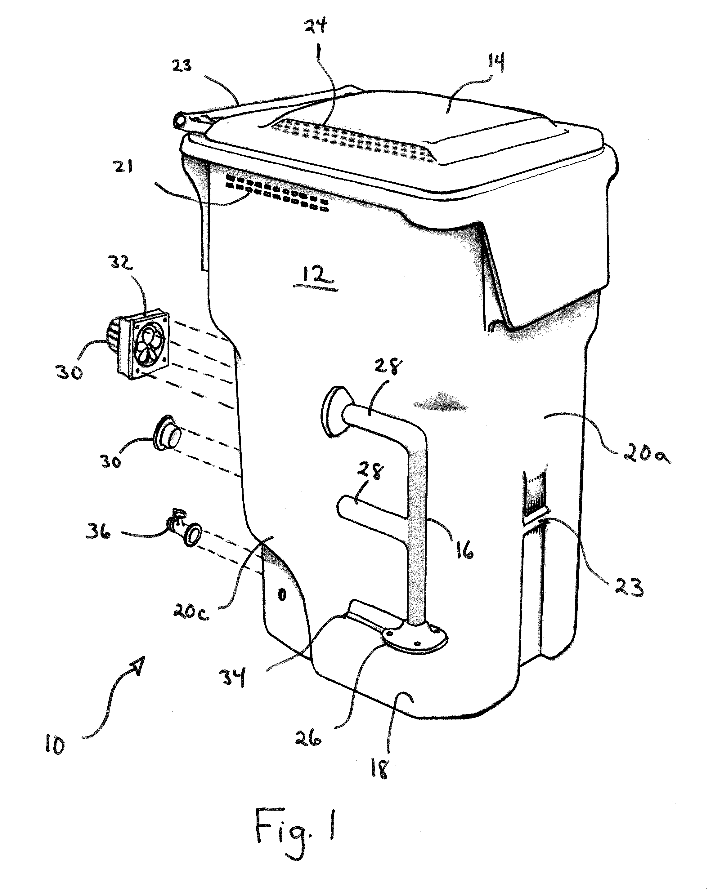
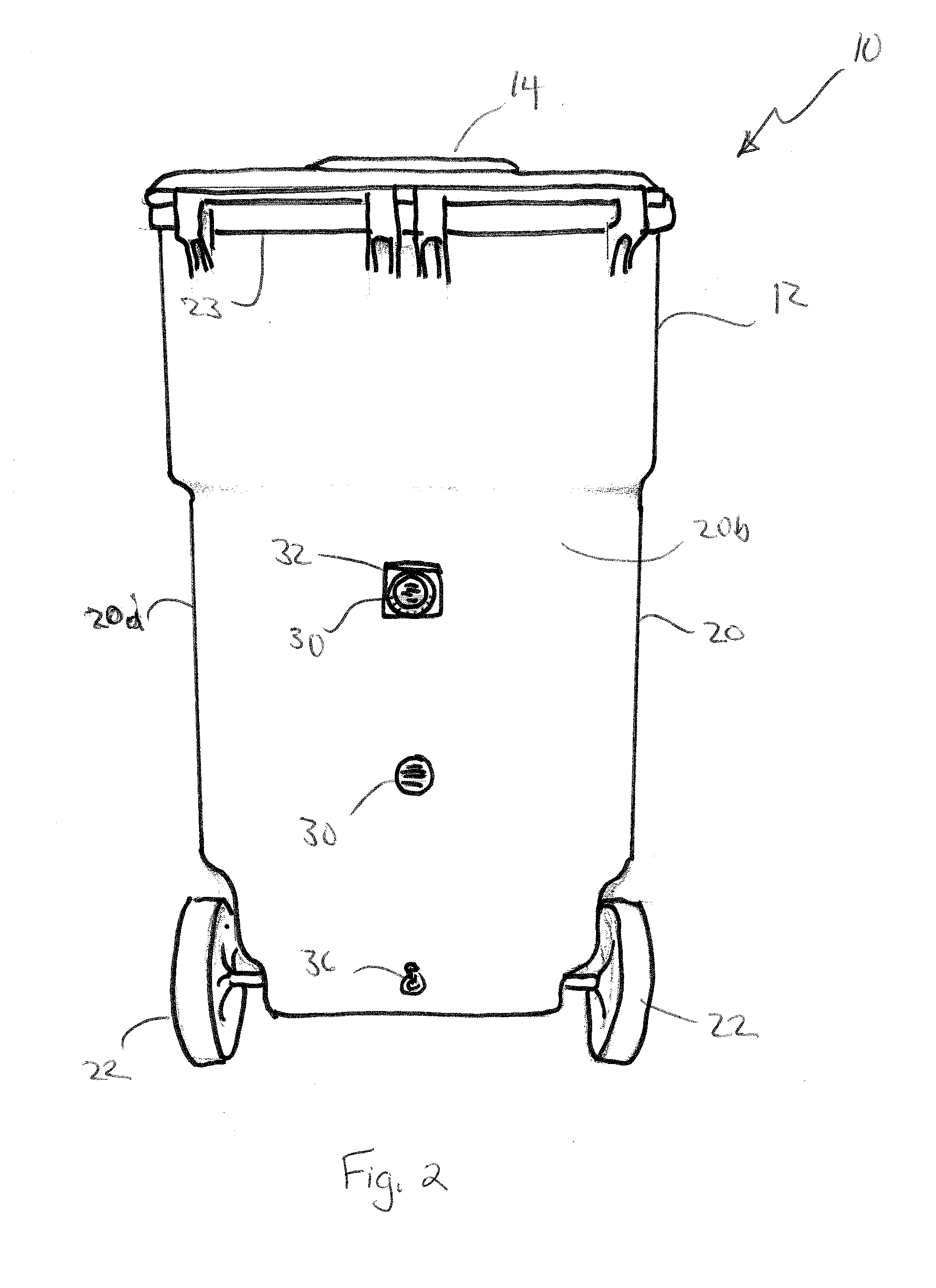
[0038]Referring now to FIG. 4, a second alternative embodiment is shown generally at 200. The second alternative embodiment 200 shows that the vent openings 30 may be located on the front 20a of the compost bin 10 in contrast to the preferred embodiment shown in FIGS. 1 and 2, where the vent openings 30 are on the rear 20b. Although not shown specifically, the vent openings 30 may also be located on the sides as well.

embodiment 300

[0039]Referring now to FIG. 5, a third alternative embodiment is shown generally at 300. The third alternative embodiment 300 includes features of the first alternative embodiment and second alternative embodiments. Specifically the compost bin includes first and second shelves 102, 104 and forward facing vent openings 30.

[0040]Referring now to FIG. 6, a fourth alternative embodiment is shown generally at 400 that includes an access door 402 on the sidewall 20 of the body portion 12 of the compost bin 10. The access door 402 is fitted within two tracks 404 and slides upwards to reveal an opening 406 into the body portion 12 of the compost bin 10. The opening 406 is preferably located near the bottom 18 of the boy portion 12 to permit the user to easily access fully composted material for use as fertilizer.

[0041]Referring now to FIGS. 7a and 7b, a fifth alternative embodiment of the compost bin is shown generally at 500. In this fifth embodiment 500, the compost bin 10 includes a hin...


PUM

PropertyMeasurementUnit
gravityaaaaaaaaaa
weightaaaaaaaaaa
movementaaaaaaaaaa

Abstract

An aerated compost and waste collection bin is disclosed. The bin includes a body portion having a bottom, at least one sidewall from the bottom, and an open top forming a container. A perforated tube extends upwards from the bottom of the body portion. At least one lateral vent tube is connected to the perforated tube and the sidewall of the body portion. The lateral vent tube allows air to circulate from outside the body portion of the bin through to the perforated tube.

Description

CROSS-REFERENCE TO RELATED APPLICATION[0001]This application claims priority to earlier filed U.S. Provisional Application Ser. No. 61 / 365,878, filed Jul. 20, 2010, the entire contents of which are incorporated herein by reference.BACKGROUND OF THE INVENTION[0002]1. Field of the Invention[0003]The present patent document relates generally to composting and waste collection and more specification to an aerated composter and organic waste collection bin.[0004]2. Background of the Related Art[0005]Composting has many benefits to the environment. Compost is a key ingredient in organic farming. At its most essential, the process of composting requires simply piling up waste outdoors and waiting a year or more.[0006]Modern, methodical composting is a multi-step, closely monitored process with measured inputs of water, air and carbon- and nitrogen-rich materials. The decomposition process is aided by shredding the plant matter, adding water and ensuring proper aeration by regularly turning...

Claims


Application Information

Patent Timeline
Patent Type & Authority Applications(United States)
IPC IPC(8): C12M1/00
CPCC05F17/0205C05F17/0276C05F17/027C05F17/907C05F17/979C05F17/986Y02W30/40Y02P20/145
Inventor BRADLEE, MICHAEL
Owner SOUTH PROVIDENCE DEV
Why Eureka
Try Eureka