A clean room system with high efficiency dehumidification

A clean room, high-efficiency technology, applied in the field of clean room, can solve the problem that the air humidity in the clean room is not easy to drop, and achieve the effect of improving the dehumidification effect, reducing the failure rate, and reducing the operating load

Active Publication Date: 2017-02-22
苏州市海魄洁净环境工程有限公司
View PDF7 Cites 0 Cited by
  • Summary
  • Abstract
  • Description
  • Claims
  • Application Information

AI Technical Summary

Problems solved by technology

[0003] In view of the above technical problems, the present invention discloses a clean room system with high efficiency dehumidification. A heat recovery device is installed on the refrigeration system, and a return air device is installed at the bottom of the clean room, which solves the problem of The problem that the air humidity in the clean room is not easy to drop, and at the same time effectively avoid the operation failure of the refrigeration equipment

Method used


Image

  • A clean room system with high efficiency dehumidification
  • A clean room system with high efficiency dehumidification
  • A clean room system with high efficiency dehumidification

Examples


Embodiment Construction

[0017] The present invention will be further described in detail below in conjunction with the accompanying drawings, so that those skilled in the art can implement it with reference to the description.

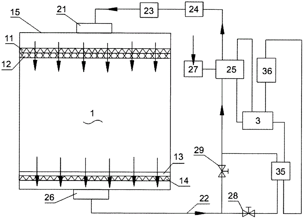
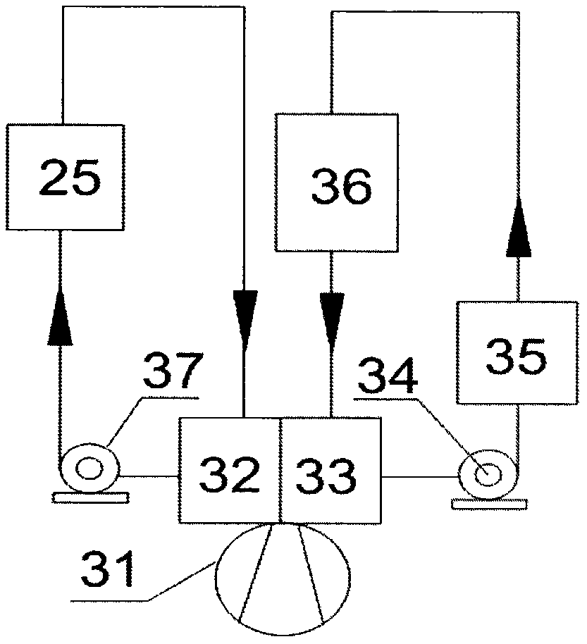
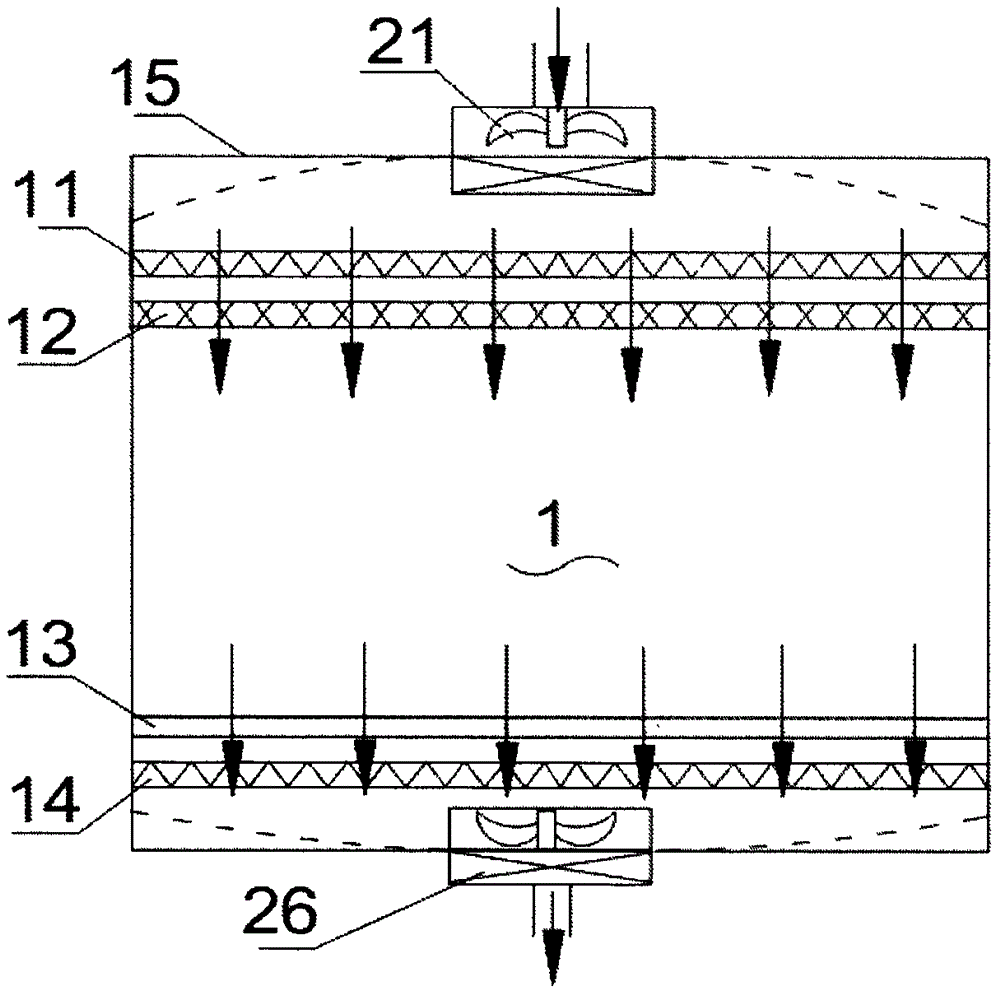
[0018] Such as Figure 1-3 As shown, a kind of efficient dehumidification clean room system provided by the present invention comprises:

[0019] The clean room 1 has an air inlet equalization device 11 arranged horizontally on its upper end, and a return air equalization device 14 is correspondingly arranged at the bottom of the clean room 1. Both the air inlet equalization device 11 and the return air equalization device 14 are assembled structures, which can be easily disassembled , they are used in conjunction to make the air flow evenly enter and flow out of the interior space of the clean room 1; the air conditioning system, which is connected to the upper end and the lower end of the clean room 1 at the same time, and the air flow uniformly flows through the interior o...


PUM


Abstract

The invention discloses an efficient dehumidification cleaning room system. The efficient dehumidification cleaning room system comprises a cleaning room, an air conditioning system and a refrigeration system, wherein an inflow air balancing device is transversely arranged at the upper end of the cleaning room, and is used for balancing air current flowing into the room; a return air balancing device is correspondingly arranged at the bottom of the cleaning room, and is used for balancing air current flowing out of the room; the air conditioning system is communicated with the upper end and the lower end of the cleaning room simultaneously; air current uniformly flows through the internal space of the cleaning room from top to bottom, and flows back into the air conditioning system to construct air current circulation; the refrigeration system is communicated with the air regulating system, and is used for regulating and controlling the temperature and humidity of the cleaning room in a heat exchange form; a heat return device is arranged on the refrigeration system, and is used for heating return air of the cleaning room; the heated return air flows through a dehumidification device so as to further lower the humidity of indoor air. The problem of difficulty in lowering the air humidity in the cleaning room is solved.

Description

technical field [0001] The invention relates to the field of clean rooms, in particular to a high-efficiency dehumidification clean room system. Background technique [0002] Clean room refers to the reduction of particulates, harmful air, bacteria and other pollutants in the air to below the specified indicators within a certain space, and the indoor temperature, humidity, cleanliness, air velocity and air distribution, noise vibration and lighting, static electricity, etc. A room specially designed to control within a certain range of needs. The clean room occupies a pivotal position in modern production technology, but in the existing technology, the humidity of the air in the clean room is not easy to drop, especially in the low temperature state, the indoor humidity cannot meet the use requirements, making the air conditioning system work continuously In the cooling state, the operating load of the equipment is increased but the dehumidification effect is not obvious, ...

Claims


Application Information

Patent Timeline
Patent Type & Authority Patents(China)
IPC IPC(8): F24F3/00F24F3/14F24F3/16
CPCF24F3/14F24F2003/005F24F2003/1446F24F8/10
Inventor 王丽芳王艮刘长安国金花计毅平孙晓来
Owner 苏州市海魄洁净环境工程有限公司
Why Eureka
Try Eureka