
Electric Power Conversion System

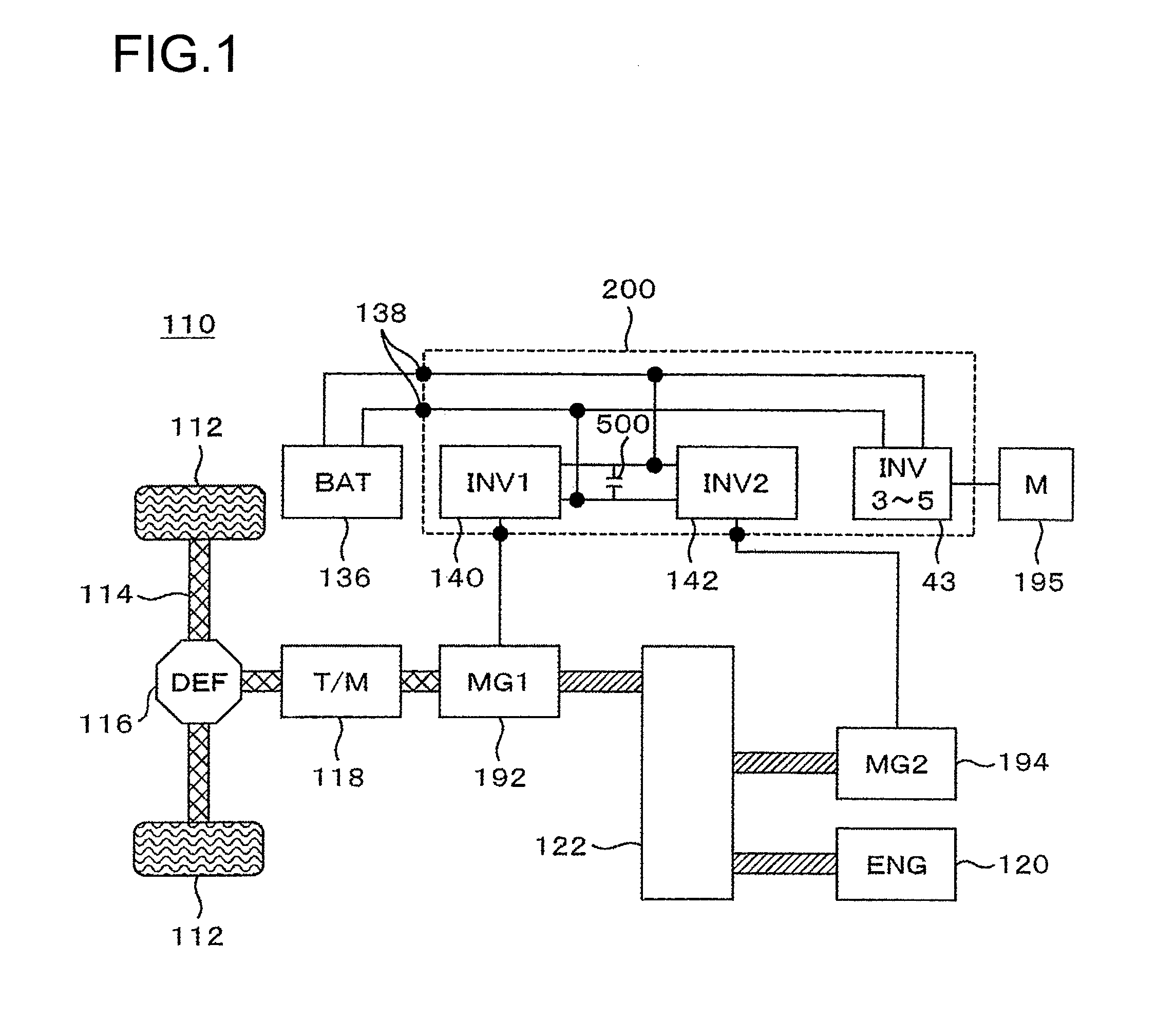
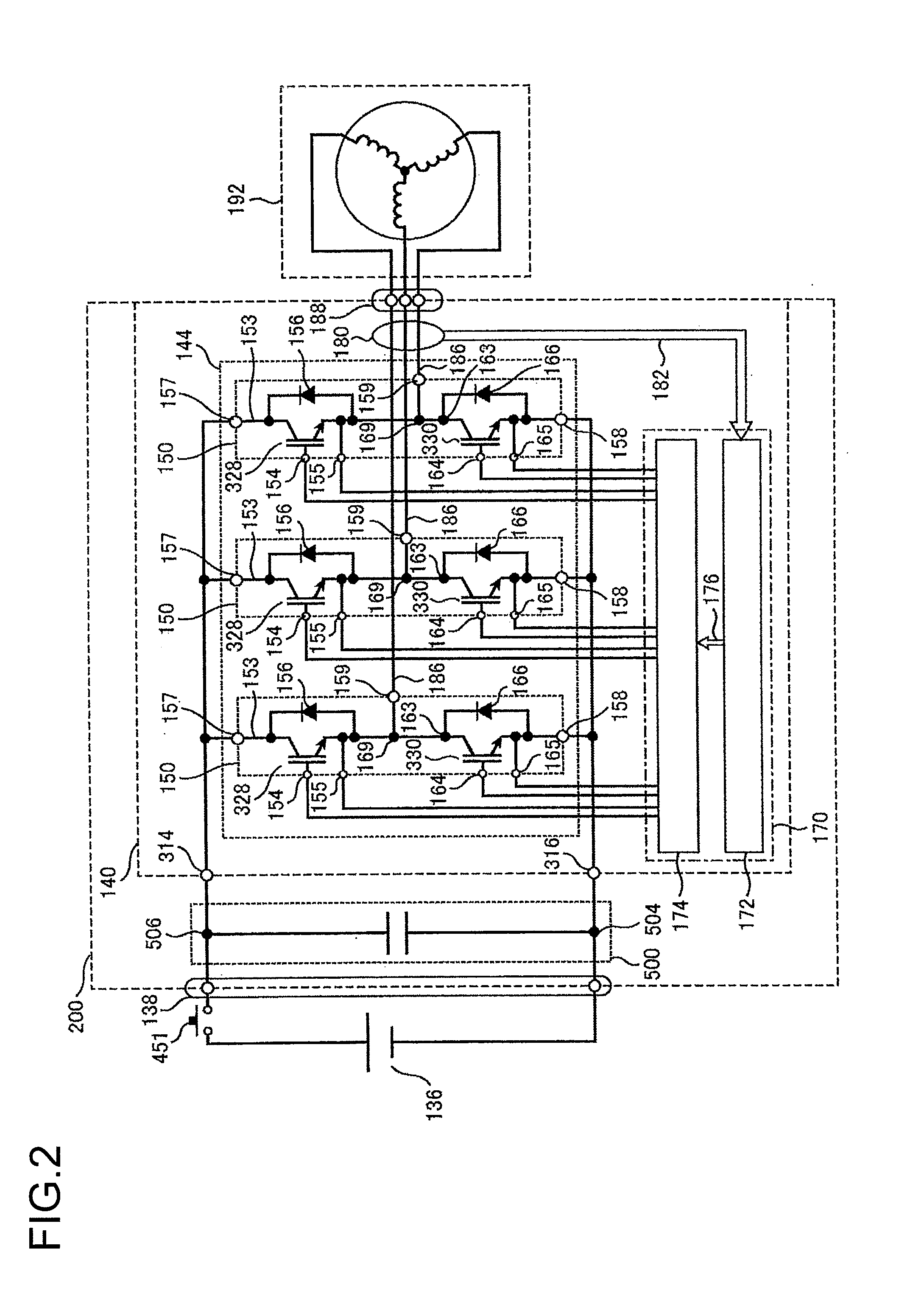
a power conversion system and discharge control technology, applied in the direction of dc-ac conversion without reversal, battery/fuel cell control arrangement, transportation and packaging, etc., can solve the problems of deterioration of the conversion efficiency of the inverter and improve the reliability of the discharge control device and the power conversion system.

Active Publication Date: 2012-01-26
HITACHI ASTEMO LTD
View PDF6 Cites 23 Cited by
  • Summary
  • Abstract
  • Description
  • Claims
  • Application Information

AI Technical Summary

Benefits of technology

[0019]With the power conversion system according to the present invention, discharging of the capacitor can be stopped by the second discharge control circuit even when the contactor or the first discharge control circuit is in failure, so that the reliability of discharge control in the power conversion system can be improved. Even when the microcomputer or the like is in failure, discharging of the capacitor can be stopped by the pulse generation circuit unit, so that the reliability of discharge control can be increased. According to the present invention, these can improve the reliability of the discharge control device and the power conversion system using the same.

Problems solved by technology

However, this method leads to heat generation by the resistor due to continuously flowing current on the discharge resistor, and also leads to a deterioration of conversion efficiency of the inverter.

Method used


Image

  • Electric Power Conversion System
  • Electric Power Conversion System
  • Electric Power Conversion System

Examples


first embodiment

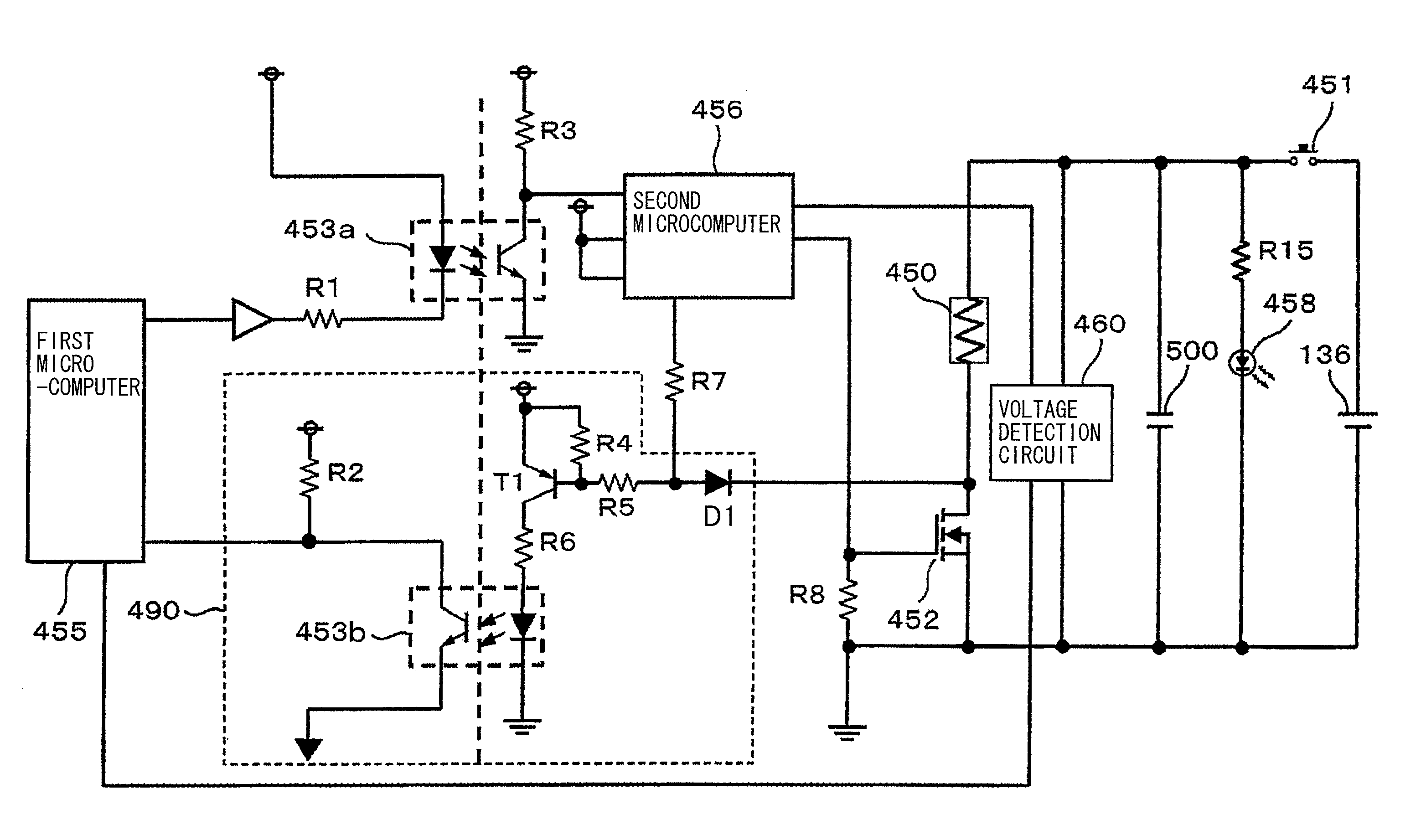
[0064]FIG. 4 shows a circuitry according to a first embodiment of the present invention.

[0065]In FIG. 4, the first discharge control circuit 470 includes a first microcomputer 455 and detects and generates a first discharge command signal (A_DCHG) based on the voltage between both terminals of the capacitor module 500 detected by the voltage detection circuit 460. The first discharge command signal (A_DCHG) is input to the second microcomputer 456 provided in the second discharge control circuit 480 through the insulated transmission element 453a such as a photocoupler.

[0066]The second microcomputer 456 generates a second discharge command signal (DCHG_FET) based on a rising edge or a falling edge of the first discharge signal (A_DCHG). According to the method of generating a discharge signal as mentioned above, when the first microcomputer 455 is in failure or erroneously operates at the time of, for example, the contactor welding, a second discharge command signal (DCHG_FET) is ou...

second embodiment

[0072]FIG. 5 shows the circuit construction of the power conversion system according to a second embodiment of the present invention. The power conversion system according to the second embodiment corresponds to a circuit which is obtained by using a one-shot IC 457 instead of the second microcomputer 456 and basic circuit operations are as explained with respect to the first embodiment shown in FIG. 4. Differences of the present embodiment from the first embodiment are explained hereafter.

[0073]The first discharge command signal (A_DCHG) output from the first microcomputer 455 is input to the one-shot IC 457 through an insulated amplifier circuit, for example, the insulated transmission element 453a. In the one-shot IC 457, a second discharge command signal (DCHG_FET) having a predetermined pulse width is generated based the rising edge or falling edge of the input signal. According to the method of generating a discharge signal as mentioned above, when the first microcomputer 455 ...


PUM


Abstract

A power conversion system according to the present invention includes: an inverter circuit unit that converts a direct current power supplied from a direct current source into an alternating current power, the direct current power being supplied to the inverter circuit through a contactor that conducts and interrupts the direct current; a capacitor that smoothes the direct current power; a discharge circuit unit that is connected to the capacitor in parallel, and that includes a discharge resistor for discharging a charge stored in the capacitor and a switching element for the discharge resistor, being connected in series to the discharge resistor; a voltage detection circuit unit that detects voltage between both terminals of the capacitor; a first discharge control circuit that includes a first microcomputer, and that outputs a control signal to control switching of the switching element for discharging; and a second discharge control circuit that outputs an interruption signal to interrupt the switching element for the discharge resistor.

Description

TECHNICAL FIELD[0001]The present invention relates to a discharge control unit for discharging charges stored in a capacitor and a electric power conversion system equipped therewith.BACKGROUND ART[0002]An inverter that is used in an electric vehicle in many cases is equipped with a capacitor for smoothing direct current voltage of the main circuit. As a method for discharging charges stored in the capacitor that remains after the switch of the inverter is turned off, there is adopted a method of connecting a discharge resistor across both ends of the capacitor. However, this method leads to heat generation by the resistor due to continuously flowing current on the discharge resistor, and also leads to a deterioration of conversion efficiency of the inverter. Therefore, a method in which a switching element or the like is connected to the discharge resistor in series so that discharging can be started by switching the switching element to be conducting by a discharge command signal ...

Claims


Application Information

Patent Timeline
Patent Type & Authority Applications(United States)
IPC IPC(8): H02M7/48
CPCB60L11/1851H02M7/48Y02T10/705Y02T10/7005H02M2001/322B60L58/10H02M1/322Y02T10/70
Inventor AKAISHI, YOSHIONOTO, YASUOYAHATA, KOICHIFUNABA, SEIJITSUJI, MASASHGE
Owner HITACHI ASTEMO LTD
Learn More