Releasable tie

a tie and releasable technology, applied in the field of cable ties, can solve the problems of inconvenient use of conventional ties, waste of resources, and inconvenient use of ties, and achieve the effect of maximizing the friction between the arm and the finger of the user

Inactive Publication Date: 2012-01-26
KS TERMINALS INC
View PDF16 Cites 8 Cited by
  • Summary
  • Abstract
  • Description
  • Claims
  • Application Information

AI Technical Summary

Benefits of technology

[0008]Hence, it is a primary objective of the present invention to provide a releasable tie having an operating rod and an arm extending therefrom, such that a user can easily exert a force on the arm extending from the operating rod and thus enable first meshing teeth of the operating rod and second meshing teeth of a band to come out of mesh easily, thereby releasing the second end of the band from a window of the locking element. Accordingly, the releasable tie is reusable to thereby save the usage costs thereof.
[0010]Yet another objective of the present invention is to provide a releasable tie characterized in that a second top side of the arm of the operating rod has a concave surface; and, optionally, the second top side of the arm has a corrugated surface. The concave surface and corrugated surface of the arm of the second top side maximize the friction between the arm and a user's finger. As a result, the user's finger can exert a force on the arm of the operating rod easily to thereby release the second end of the band from the window of the locking element easily. Accordingly, the releasable tie is easy to operate.
[0011]Still yet another objective of the present invention is to provide a releasable tie characterized in that the window of the locking element has a transverse opening in alignment with the first walls, wherein the transverse opening is larger than the width of the band; and the window has a vertical opening perpendicular to the transverse opening, wherein the vertical opening is larger than the thickness of the band. Accordingly it is easy to pass the band through the window of the locking element, and easy to pull the second end of the band, so as to bundle and tuck objects.

Problems solved by technology

However, once tied up, the tie cannot be loosened.
Thus, conventional ties are inconvenient to use, cost-inefficient, and a waste of resources.

Method used


Image

  • Releasable tie
  • Releasable tie
  • Releasable tie

Examples


Embodiment Construction

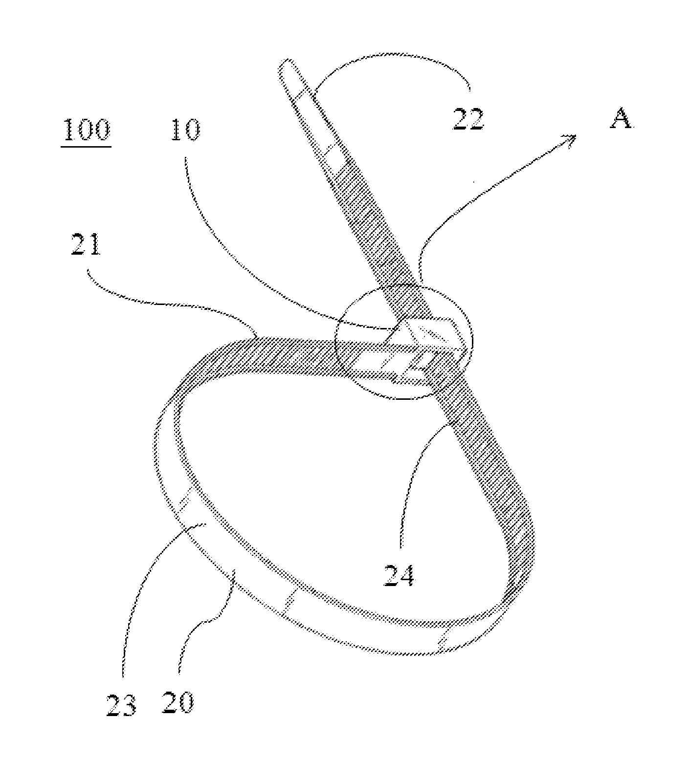
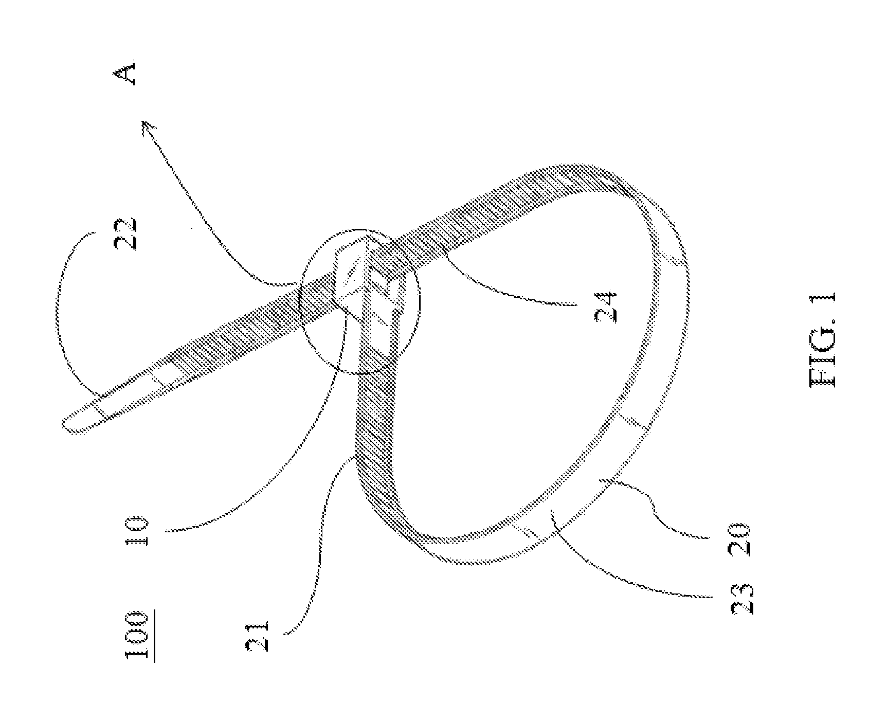
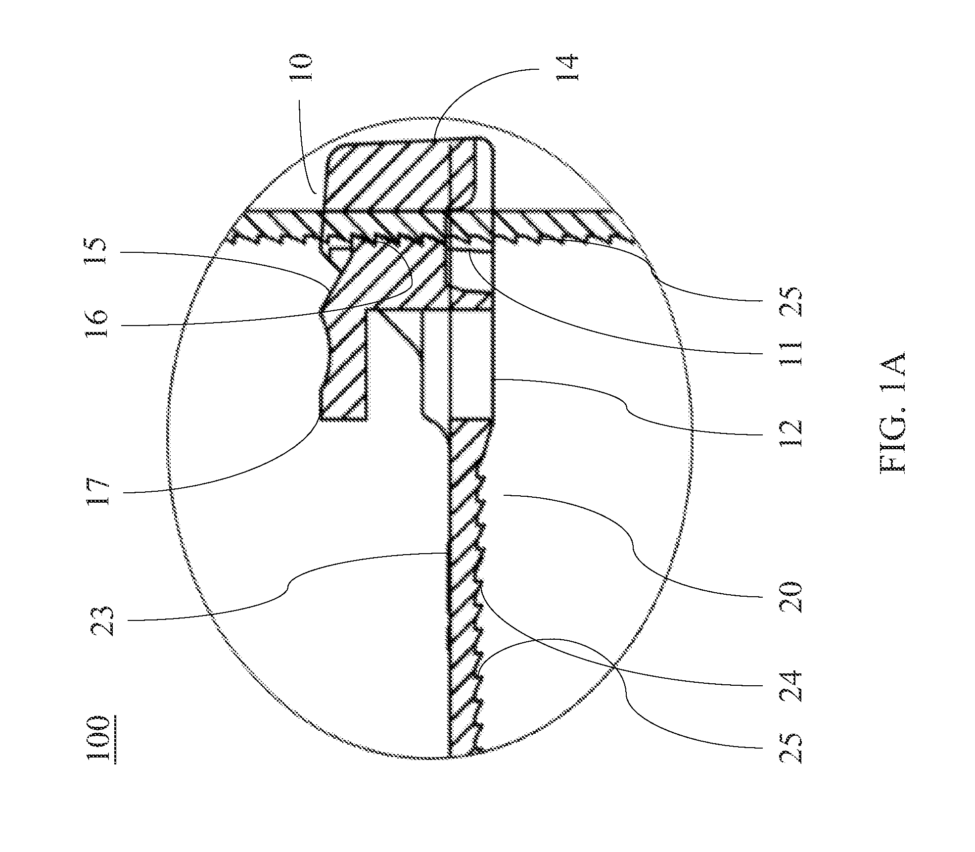
[0019]Referring to FIG. 1 and FIG. 1A, there are shown a perspective view of a releasable tie 100 in a preferred embodiment according to the present invention and an enlarged partial cross-sectional view of portion A shown in FIG. 1. As shown in the drawings, the releasable tie 100 comprises a locking element 10 and a band 20. The locking element 10 is formed with a window 11. The band 20 has a first end 21 and a second end 22. The first end 21 is connected to the locking element 10. The second end 22 penetrates the window 11 of the locking element 10 to fixedly engage the locking element 10, thereby bundling objects to be tied up.

[0020]Referring to FIG. 2, there is shown a perspective view of the releasable tie 100 in another preferred embodiment according to the present invention. The locking element 10 has a bottom plate 12, paired first walls 13, a second wall 14, and an operating rod 15. The bottom plate 12 has a front end 121 and a rear end 122. The first end 21 of the band 20...


PUM


Abstract

A releasable tie includes a locking element and a band. The band has first and second ends. The locking element includes a bottom plate, first walls, a second wall, and an operating rod. The bottom plate is formed with a window. A predefined gap is formed between the operating rod and the first walls. The operating rod has an arm extending therefrom and first meshing teeth thereon. An aperture is formed at such a position on the bottom plate that the projection of the arm lies at the position on the bottom plate. The band has a first top side and a bottom side with second meshing teeth thereon. The first and second meshing teeth are in mesh. The band is thinner than the bottom plate. The thickness of the band is larger than the distance between the top end of the first meshing teeth and the second wall.

Description

BACKGROUND OF THE INVENTION[0001]1. Technical Field[0002]The present invention relates to cable ties, and more particularly, to a releasable tie.[0003]2. Description of Related Art[0004]Normally, commercially available ties hold typical power lines or objects together or serve a tightening, fixing or tucking purpose. However, once tied up, the tie cannot be loosened. To add an object to tie, or to tuck objects tied up anew, it is necessary to sever the tie and use a new one. Thus, conventional ties are inconvenient to use, cost-inefficient, and a waste of resources.SUMMARY OF THE INVENTION[0005]In order to overcome the aforesaid drawbacks of the prior art, the present invention provides a releasable tie. The releasable tie comprises a locking element and a band. The locking element is formed with a window. The band has a first end and a second end. The first end is connected to the locking element. The second end penetrates the window to fixedly engage the locking element.[0006]Furt...

Claims


Application Information

Patent Timeline
Patent Type & Authority Applications(United States)
IPC IPC(8): B65D63/00
CPCY10T24/14B65D63/1072
Inventor CHENG, JUEI-CHING
Owner KS TERMINALS INC
Why Eureka
Try Eureka