Aircraft assembly and spar

a technology for aircraft and parts, applied in the field of aircraft assembly, can solve the problems of high scrap level, notoriously expensive manual process, and increased cost, and achieve the effect of maintenance, reducing the cost of production, and increasing the cost of production

Inactive Publication Date: 2012-01-19
AIRBUS OPERATIONS LTD
View PDF18 Cites 19 Cited by
  • Summary
  • Abstract
  • Description
  • Claims
  • Application Information

AI Technical Summary

Benefits of technology

[0013]Integrally forming the spar web and at least part of the container as a single piece enables the spar web to be relatively shallow because it is no longer necessary to provide relatively flat sections of spar web around the container to accommodate a flange at the base of the container.
[0024]The spar may consist of a web only (without spar caps), or it may be formed integrally with another part such as a wing cover. Alternatively the spar may further comprise a spar cap which is integrally formed as a single piece with the spar web and extends along a substantial length of the spar. Such a flange can be used to attach the spar to a cover or other part. Typically the depth of the integrally formed part of the container measured in a direction normal to the spar web is between 70% and 300% of the depth of the spar cap immediately adjacent to the container in a direction normal to the spar web. The track container is thus sufficiently deep to house at least part of a system component such as a flap track, whilst being sufficiently shallow to be relatively easy to form integrally with the spar web.
[0026]Integrally forming the spar web and the container flange as a single piece enables the spar web to be relatively shallow because it is no longer necessary to provide relatively flat sections of spar web around the container flange to accommodate a flange at the base of the container.

Problems solved by technology

Track cans are traditionally fabricated as a welded aluminium assembly, which is a notoriously expensive manual process requiring skilled personnel a long time to fabricate.
This combination invariably results in a high level of scrap and hence greater expense.
Track cans also present significant problems from a mounting point of view.
This is time consuming and subject to leakage, resulting in greater expense.
Further to these problems are the issues which arise when track cans are used within composite wing box construction.
Combining these two problems results in conflicts between track cans and other wing box components.
Similar problems exist in relation to other system components which are normally housed in the leading or trailing edge of an aircraft wing: for instance transformers for an electrical de-icing system, or actuator units for driving a slat deployment mechanism.
Although the above discussion has focused on the aircraft wing, similar problems also exist in relation to other aerodynamic parts of the aircraft such as the vertical tail plane and horizontal tail plane.

Method used


Image

  • Aircraft assembly and spar
  • Aircraft assembly and spar
  • Aircraft assembly and spar

Examples


Embodiment Construction

)

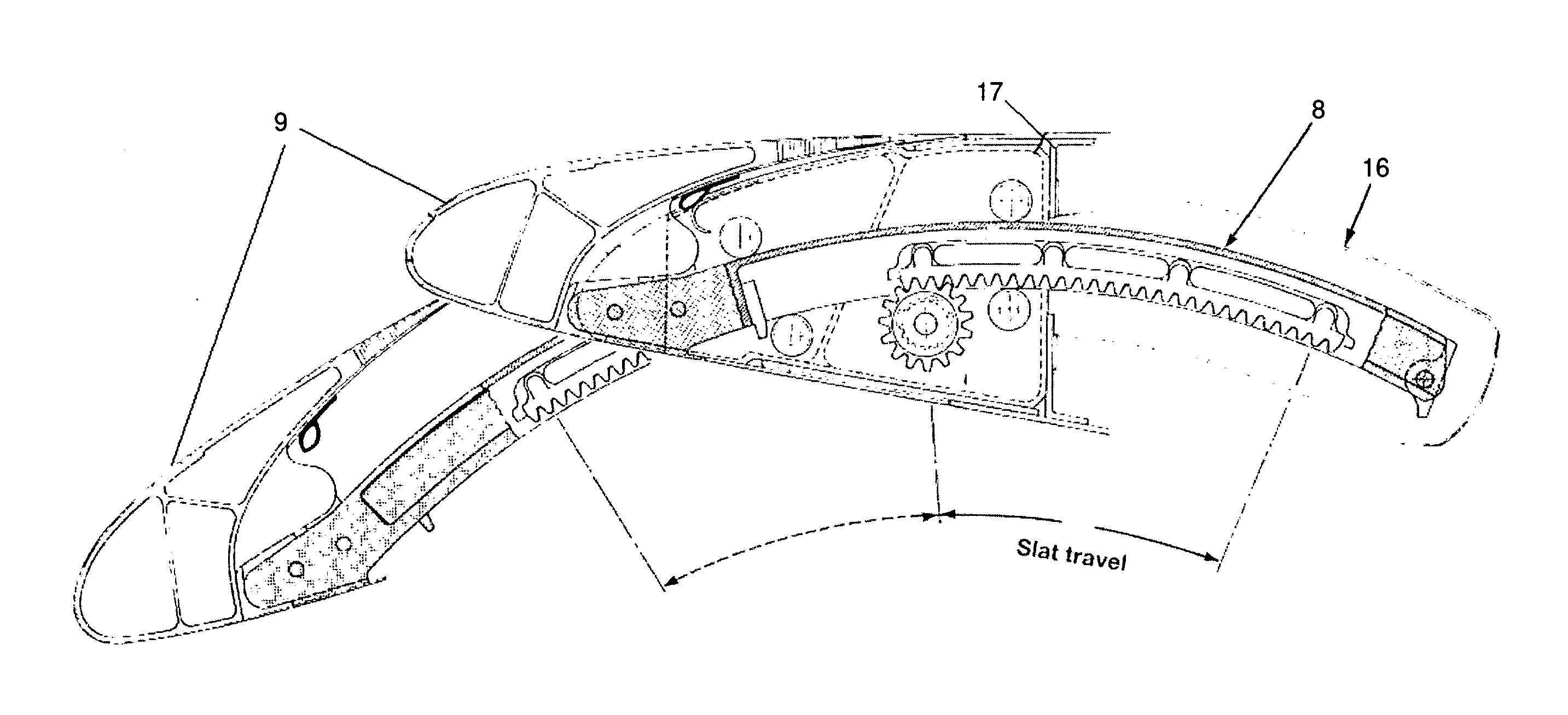
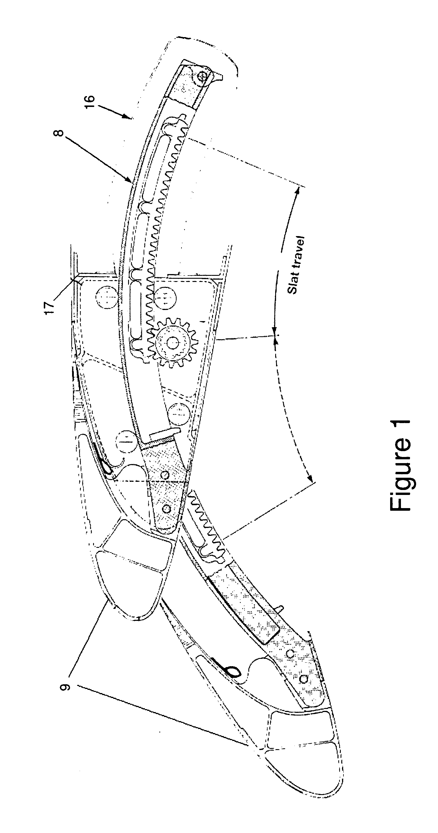
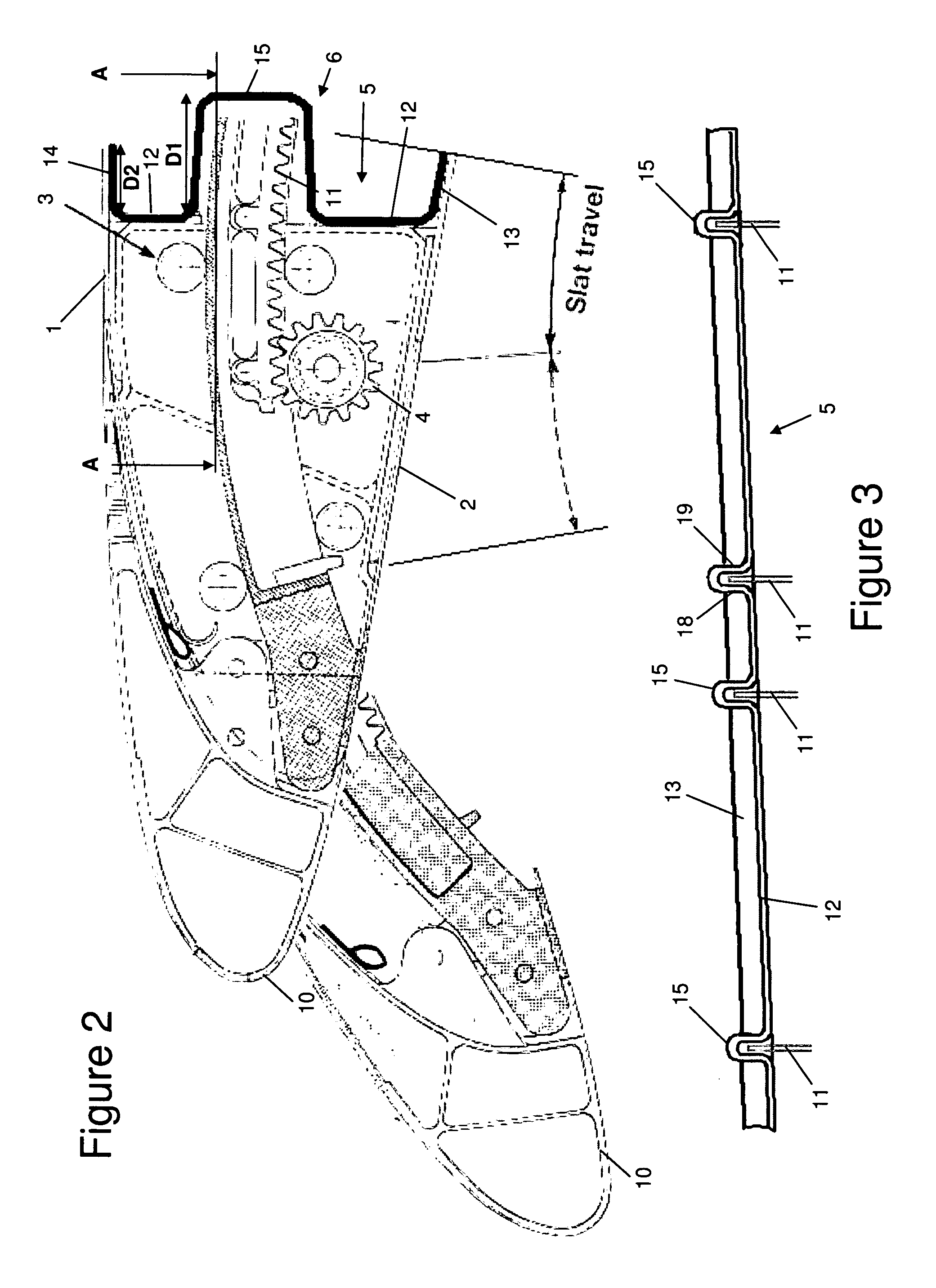
[0038]The leading edge of an aircraft wing assembly is shown in FIG. 2. The wing has an upper cover 1; a lower cover 2 and a front spar 5 extending between them. A fuel tank is located behind the front spar. A slat track 11 carrying a slat 10 is driven by a pinion gear 4 along a curved path defined by a set of rollers 3 between a retracted low-lift cruise position, an intermediate take-off and climb position, and a fully extended high-lift landing position. FIG. 2 shows the slat in both extreme ends of its movement. As the slat track 11 moves, its rear end slides in and out of a slat track container 6 in the front spar 5.

[0039]Note that FIG. 2 is a schematic view only, illustrated as a variation on the conventional assembly of FIG. 1. Development in aircraft wing high lift devices are such that, from a slat configuration point of view, required sufficient aerodynamic performance can be achieved with reduced slat travel. Thus the slat track 11 (and its associated travel) has been tr...


PUM

PropertyMeasurementUnit
Angleaaaaaaaaaa
Angleaaaaaaaaaa
Angleaaaaaaaaaa

Abstract

An aircraft assembly comprising: a pair of covers; a spar web extending between the covers in a thickness direction, the spar web having a length which extends in a span-wise direction; and a container which extends from the spar web and houses at least part of a system component. The container comprises first and second side walls which are spaced apart from each other across the spar web in the thickness direction, and inboard and outboard walls which are spaced apart from each other along the spar web in the span-wise direction. The spar web and at least part of the container are integrally formed as a single piece. Typically the assembly is a wing assembly with a fuel tank; a track; a high-lift device carried by the track; an actuation mechanism for moving the track and high-lift device between an extended high-lift position and a retracted low-lift position; and a track container which extends from the spar web into the fuel tank and houses at least part of the track when it is in its retracted low-lift position. The spar web and at least part of the track container are integrally formed as a single piece, typically from a laminar composite material.

Description

FIELD OF THE INVENTION[0001]The present invention relates to an aircraft assembly comprising: a pair of covers; a spar web extending between the covers; and a container which extends from the spar web and houses at least part of a system component. The invention also relates to a spar suitable for use in such an assembly. The system component may comprise a track for a high-lift device such as a slat.BACKGROUND OF THE INVENTION[0002]In order to provide aircraft operators with sufficient high lift performance in critical stages of a flight, aircraft wings have been designed to have deployable and retractable slats along the leading edge. This has historically been achieved by mounting the slats on pairs of curved slat tracks, which are driven from their respective stowed and extended positions by a rack and pinion mechanism. Aircraft wings are used to store the fuel required for the flight and as such maximising the volume available for the fuel is important. For this reason the fron...

Claims


Application Information

Patent Timeline
IPC IPC(8): B64C9/00B64C3/18B29C70/30B64C1/06
CPCB64C3/28Y02T50/433Y02T50/44B64C9/22Y02T50/40
Inventor EDEN, JAMES
Owner AIRBUS OPERATIONS LTD
Why Eureka
Try Eureka