
Image coding device and image coding method

a coding device and image technology, applied in the field of reference picture determination methods, can solve the problems of noise in the decoded image, the conventional method does not define the correlation between the motion search range (i.e., the reference field) and the motion size, and achieve the effect of reducing noise and reducing the amount of calculation required for motion estimation

Inactive Publication Date: 2012-01-12
PANASONIC CORP
View PDF3 Cites 8 Cited by
  • Summary
  • Abstract
  • Description
  • Claims
  • Application Information

AI Technical Summary

Benefits of technology

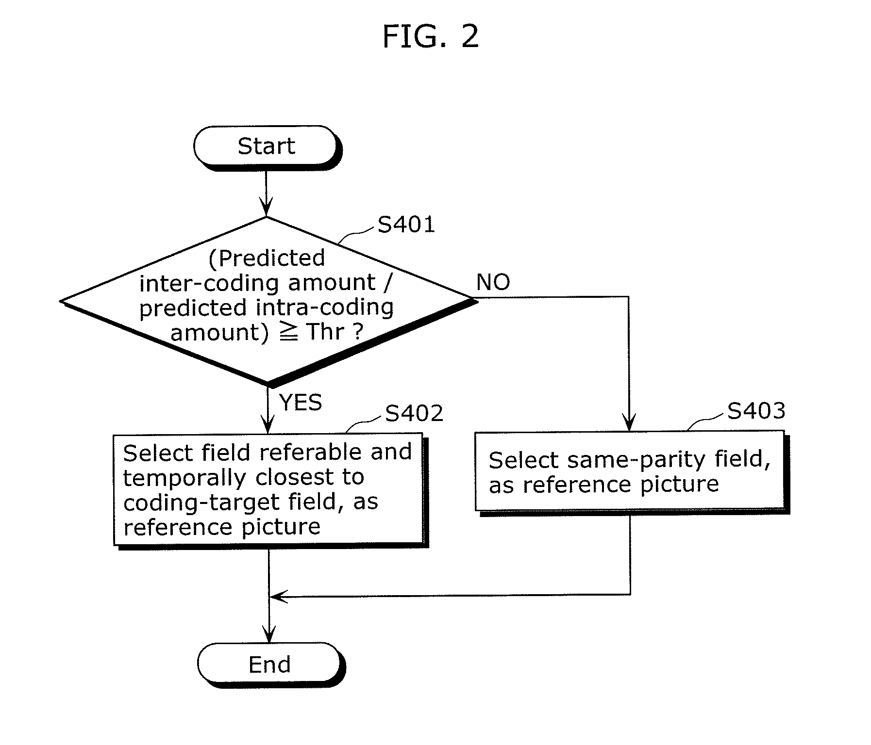
[0017]The conventional method reduces the number of reference pictures without any loss in picture quality, by using, as the reference picture, the same-parity field in the case of a small motion and the temporally-closest referable field, namely, the opposite-parity field in the case of a large motion. That is to say, the reference field is switched based on the motion size.
[0031]According to the present invention, the reference picture can be switched between the same-parity field and the temporally-closest referable field, at the timing appropriate to the coding-target field. This can reduce noise which may occur to the decoded image as a result of the reference field switching. Moreover, since two reference pictures can be used at the maximum, the memory access to the reference pictures and the amount of calculation required for the motion estimation can be reduced.FURTHER INFORMATION ABOUT TECHNICAL BACKGROUND TO THIS APPLICATION

Problems solved by technology

However, the conventional methods have the problems as follows.
However, the conventional method does not define a correlation between a motion search range (i.e., a reference field) and a motion size.
This leads to a problem that a resultant decoded image may possibly have noise.

Method used


Image

  • Image coding device and image coding method
  • Image coding device and image coding method
  • Image coding device and image coding method

Examples


first embodiment

[Configuration of Image Coding Device]

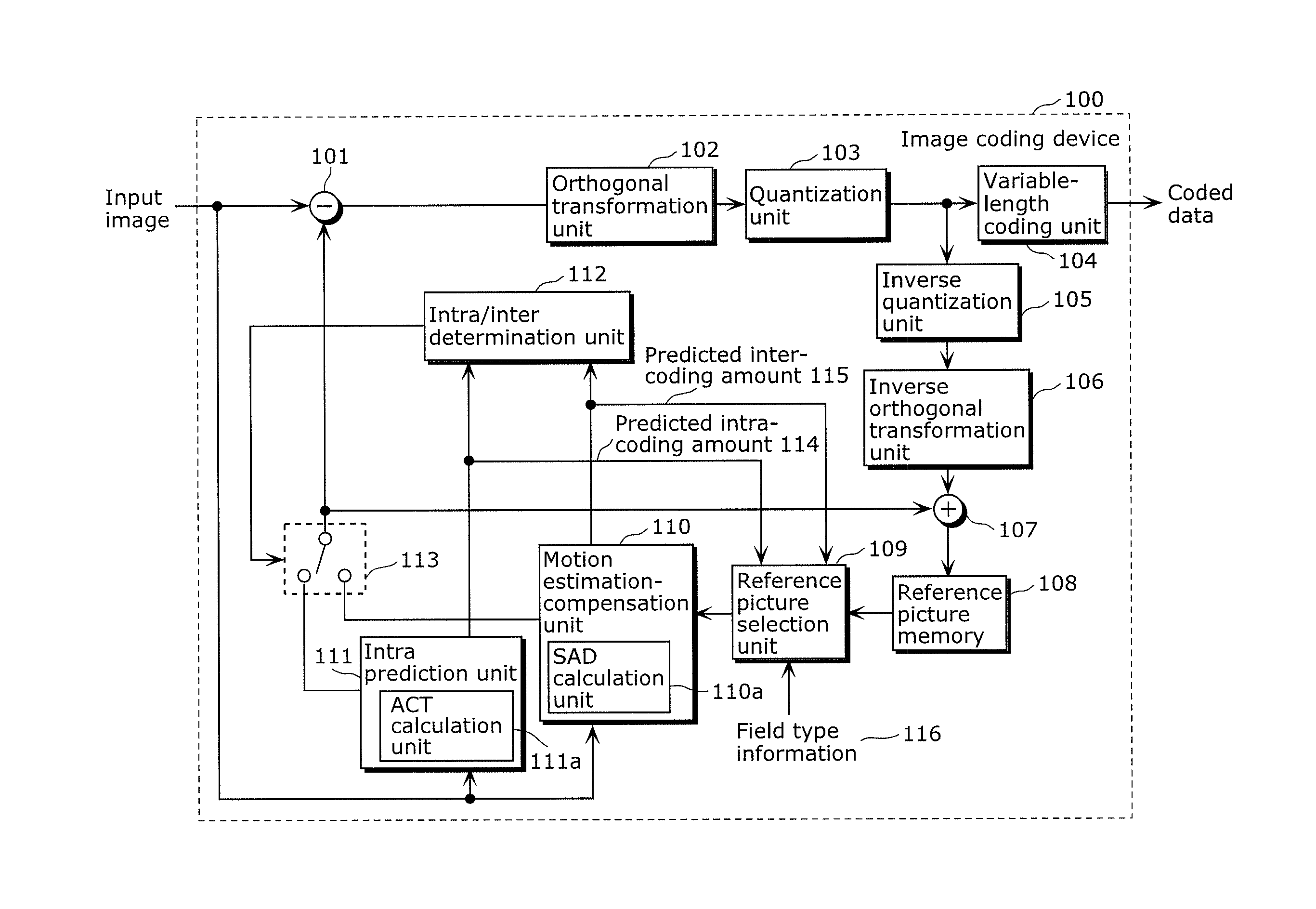
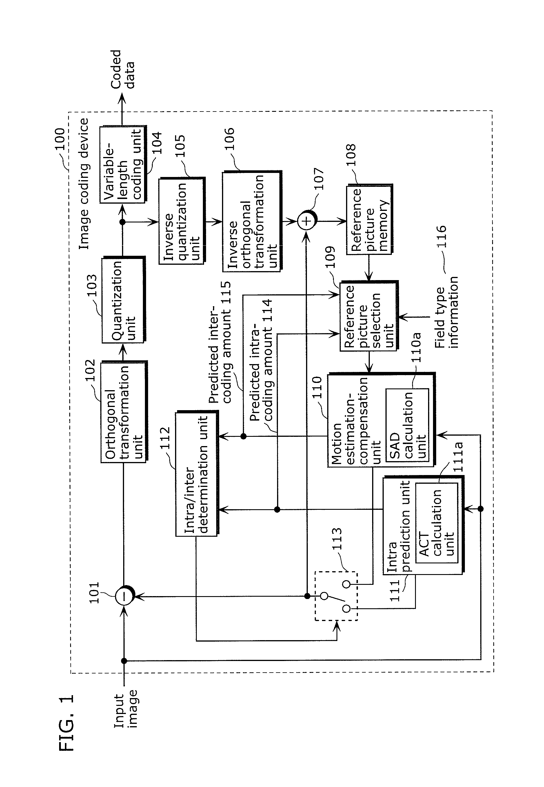
[0057]FIG. 1 is a block diagram showing a configuration of an image coding device in the first embodiment according to the present invention.

[0058]An image coding device 100 codes a received image and outputs the coded data. The image coding device 100 includes a subtracter 101, an orthogonal transformation unit 102, a quantization unit 103, a variable-length coding unit 104, an inverse quantization unit 105, an inverse orthogonal transformation unit 106, an adder 107, a reference picture memory 108, and a reference picture selection unit 109, a motion estimation-compensation unit 110, an intra prediction unit 111, an intra / inter determination unit 112, and a selector 113.

[0059]The subtracter 101 calculates a difference between an input image received from an external source and a reference picture received from the motion estimation-compensation unit 110, and outputs difference data indicating a result of the calculation.

[0060]The orthogonal tr...

first modification

of First Embodiment

[0099]The first embodiment has described that it is appropriate to use the SAD and the ACT for scene determination. However, when natural scenery is actually shot and SAD / ACT is calculated, a resultant graph is not as smooth as the graph shown in FIG. 4C. It can be easily assumed that the actual graph includes abrupt changes like pulse noise, as shown in FIG. 7A. It should be noted that FIG. 7A shows abrupt changes only at nine positions in the graph for the sake of convenience and that, in reality, abrupt changes occur everywhere in the graph.

[0100]In the case where a natural scene image is coded and the reference picture switching is performed using only one determination threshold Thr of SAD / ACT as in the first embodiment, the reference picture is switched frequently when the SAD / ACT value is around the determination threshold Thr. As a result, errors in the motion estimation increase and the coding efficiency decreases.

[0101]To address this, the first modifica...

second modification

of First Embodiment

[0111]As described in the first modification above, when natural scenery is actually shot, a resultant graph is not as smooth as the graph shown in FIG. 4C. It can be easily assumed that the actual graph includes abrupt changes like pulse noise, as shown in FIG. 7A. It should be noted that FIG. 7A shows abrupt changes only at nine positions in the graph and that, in reality, abrupt changes occur everywhere in the graph.

[0112]In the case where a natural scene image is coded and the reference picture switching is performed using only one determination threshold Thr of SAD / ACT as in the first embodiment, the reference picture switching is performed frequently when the SAD / ACT value is around the determination threshold Thr. As a result, errors in the motion estimation increase and the coding efficiency decreases.

[0113]To address this, the second modification of the first embodiment describes a method capable of correctly selecting the reference picture even in the ab...


PUM


Abstract

A reference picture selection unit compares a predicted inter-coding amount indicating a predicted amount of coding required to perform inter prediction on a coding-target field and a predicted intra-coding amount indicating a predicted amount of coding required to perform intra prediction on the coding-target field. Upon determining that the predicted inter-coding amount is relatively larger than the predicted intra-coding amount, the reference picture selection unit switches the reference picture from a field having the same parity as the coding-target field to a field which is referable and temporally closest to the coding-target field.

Description

CROSS REFERENCE TO RELATED APPLICATION[0001]This is a continuation application of PCT application No. PCT / JP2009 / 006718 filed on Dec. 9, 2009, designating the United States of America.BACKGROUND OF THE INVENTION[0002](1) Field of the Invention[0003]The present invention relates to a reference picture determination method used when interlaced coding is performed in video signal compression. In particular, the present invention provides a method of selecting a reference picture according to a predicted intra-coding amount and a predicted inter-coding amount to reduce the number of times data stored in a memory is accessed.[0004](2) Description of the Related Art[0005]In general, data compression in video coding is performed to reduce the quantity of data by reducing spatio-temporal redundancy in a video signal. In inter predictive coding executed for the purpose of reducing the temporal redundancy, motion estimation is performed on a coding-target picture on a block by block basis usi...

Claims


Application Information

Patent Timeline
Patent Type & Authority Applications(United States)
IPC IPC(8): H04N7/32H04N19/12H04N19/50H04N19/134H04N19/136H04N19/14H04N19/146H04N19/196H04N19/423H04N19/503H04N19/51H04N19/513H04N19/593H04N19/60H04N19/61H04N19/85H04N19/91
CPCH04N19/105H04N19/196H04N19/149H04N19/198H04N19/61H04N19/107H04N19/14H04N19/169
Inventor SASAKI, YOSHIMITSUKITAMURA, SHINJITANAKA, YASUHARU
Owner PANASONIC CORP
Learn More