
Optical arrangement for varying an imaging ratio or of a refractive power

a technology of optical arrangement and refractive power, can solve the problems of occupying entire lists of disadvantages of all solutions, and can be applied in the field of optical arrangement, which can solve the problems of amplification of the problem, the inability to adjust the image,

Inactive Publication Date: 2012-01-12
FUTURE OPTICS GBR
View PDF2 Cites 14 Cited by
  • Summary
  • Abstract
  • Description
  • Claims
  • Application Information

AI Technical Summary

Benefits of technology

[0012]According to one or more embodiments of the instant invention an optical arrangement for varying the imaging ratio and / or the refractive power is provided, which is cost-efficient, quick, compact, short, possibly two-dimensional, comprising a wide dynamic range with a high optical quality in all or almost all areas of use, possibly continuously or at least almost continuously, which can be developed easily, set up and adjusted easily and which can be controlled easily and which have small moments, if moved, and a low energy demand. Such a solution will be presented below in stages.
[0049]It may be advantageous for some applications that the optical arrangement according to one or more embodiments of the invention and / or the device including it includes a further device, which has the effect that this optical arrangement can receive radiation from at least two different solid angles and / or can send in at least two solid angles. Such a device can be an adjustable mirror and / or a rotating mirror and / or a rotating prism and / or two prisms or optical wedges rotating against one another and / or a tilting device and / or a pivoting device and / or a rotating device and / or an electrically and / or magnetically controlling deflecting device. The applications, which necessitate such a device, could include a surveillance camera, a webcam, a bio scanner, e.g. for pupil or face recognition or a driver assistance system in a vehicle, wherein a vehicle is to be understood as any mobile technical and non-technical system comprising its own drive.

Problems solved by technology

However, the disadvantages of all of the solutions fill entire lists.
The professional field comprising the same instruments and additionally telescopes, microscopes, stereomicroscopes, microscopes for medical procedures, magnifying glasses and microscopes worn on the head, also for medical procedures as well as for precision work, endoscopes, barcode readers, bio scanners, etc., is not actually satisfied with the present solutions.

Method used


Image

  • Optical arrangement for varying an imaging ratio or of a refractive power
  • Optical arrangement for varying an imaging ratio or of a refractive power
  • Optical arrangement for varying an imaging ratio or of a refractive power

Examples


Embodiment Construction

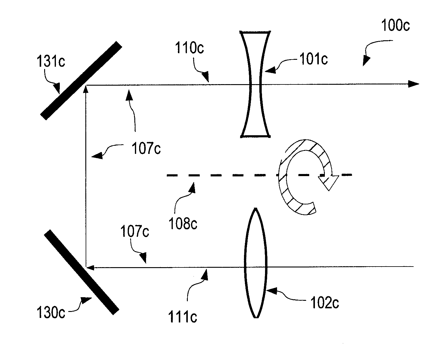
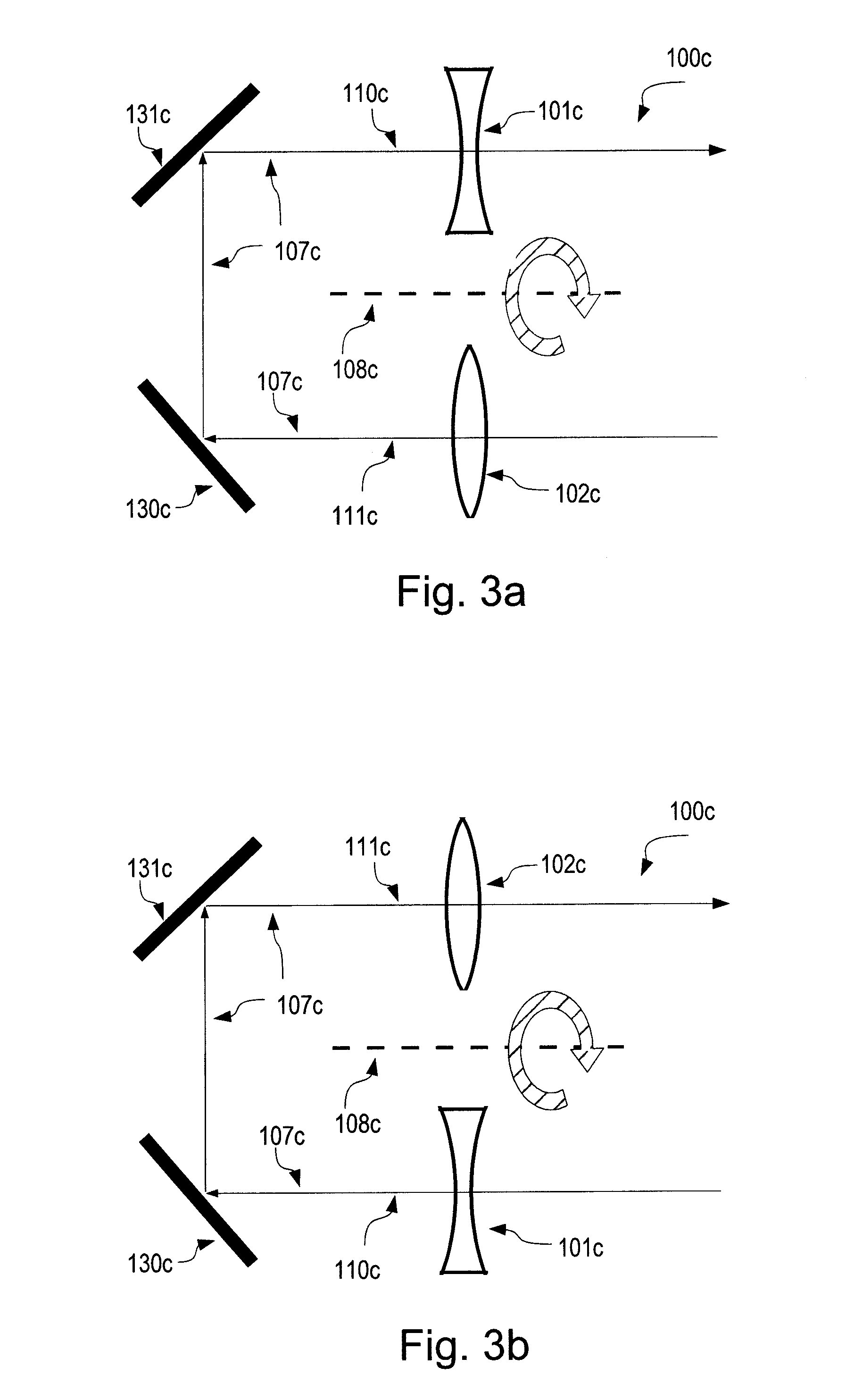
[0081]The invention is not limited to the illustrated exemplary embodiments, but is only limited by the claims. As shown, the optical elements can thus be lenses, but they can also be replaced by other optical elements. The deflection angles and the numbers of deflections can be different, without leaving the scope of protection. All combinations of the presented arrangements, the number of which is very high, also fall within the scope of protection of the invention.

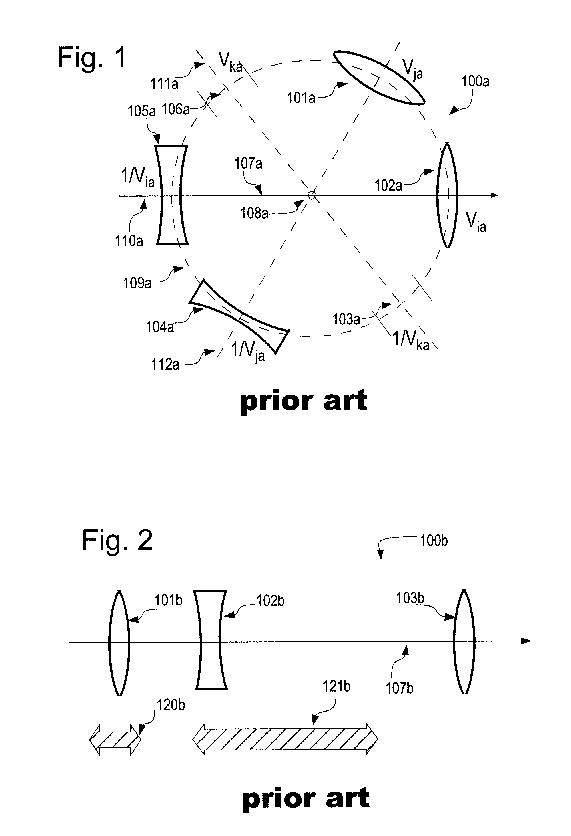
[0082]FIG. 1 illustrates an optical arrangement 100a for varying an imaging ratio and / or a refractive power in discrete steps, belonging to the state of the art. The lenses 101a, 102a, 104a and 105a, assembled on a drum or on a laterally arranged star-shaped support, e.g., can be rotated about the mechanical movement axis 108a on the circular path 109a and can thus be pivoted into the optical path with the optical axis 107a. Each lens pair encompasses a common optical axis 110a, 111a or 112a and can be positioned in two...


PUM


Abstract

Introduced is an optical arrangement for varying an imaging ratio and / or a refractive power including at least one optical axis, having at least two optical elements, which can be pivoted into and / or pivoted to and / or switched into and / or switched to the optical path, which encompass in each case a refractive power and an optical axis and the optical axes of which can in each case be made to be substantially congruent with the optical axis of the arrangement or are substantially congruent with the optical axis of the arrangement. The optical path between the optical elements, which can be pivoted into and / or pivoted to and / or switched into and / or switched to, undergoes at least one change in direction and / or vergence.

Description

BACKGROUND OF INVENTION[0001]1. Field of the Disclosure[0002]The invention relates to an optical arrangement according to the preamble of claim 1.[0003]2. Description of Related Art[0004]Optical arrangements and devices for varying an imaging ratio or of a refractive power have been known for a long time. The varifocal lenses, for instance, have already been mentioned since the first half of the 19th century in the Proceedings of the Royal Academy. Contrary thereto, an application for a patent for a first optical arrangement for continuously varying an imaging ratio with a stationary image was filed in 1902 (U.S. Pat. No. 696,788). An arrangement for varying an imaging ratio in discrete steps in the form of a drum comprising different pairs of optical elements by means of a refractive power also dates back at least to the first half of the 20th century (e.g.: DE 1 284 117, in which the issue of further intermediate steps in response to the varying of an imaging ratio is broached).[0...

Claims


Application Information

Patent Timeline
IPC IPC(8): G09G5/00G02B15/02
CPCG02B26/00G02B15/00G02B3/14G02B7/16G02B15/04G02B26/005
Inventor MAIOROVA, TATIANA
Owner FUTURE OPTICS GBR
Learn More