Connecting rod with a handle

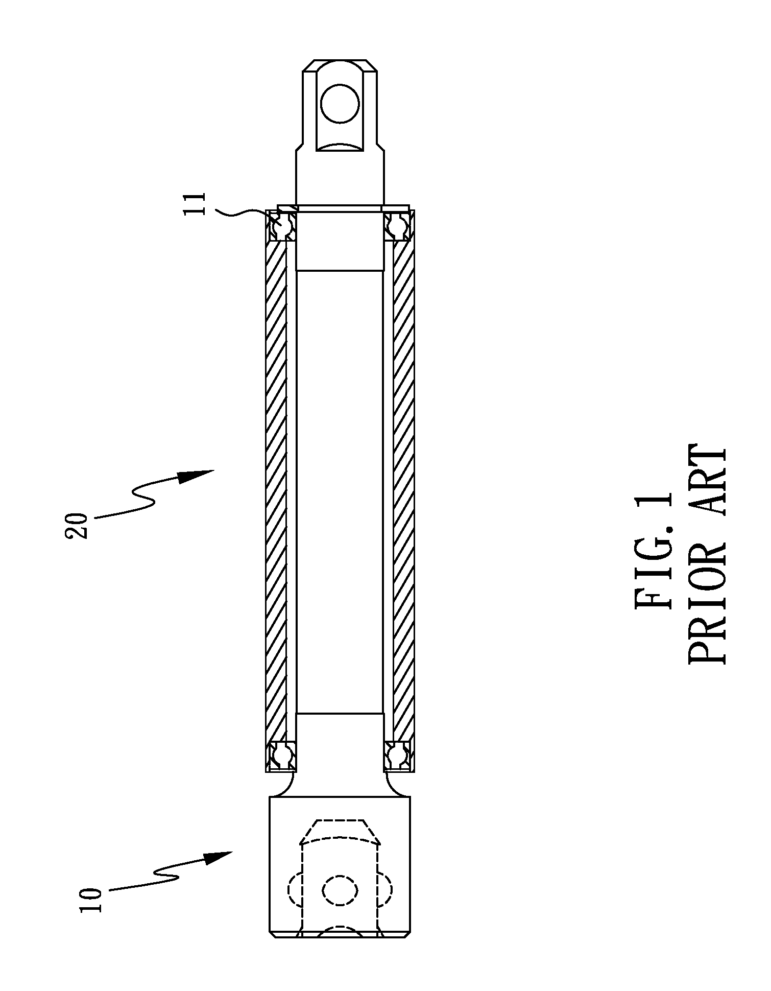
a technology of connecting rods and handles, applied in the direction of rigid support of bearings, couplings, mechanical devices, etc., can solve the problems of unfavorable handle rotation or even failure, and achieve the effect of reducing the probability of damage to parts and extending the service life of connecting rods

Inactive Publication Date: 2012-01-05
LU SU LAN
View PDF5 Cites 0 Cited by
  • Summary
  • Abstract
  • Description
  • Claims
  • Application Information

AI Technical Summary

Benefits of technology

[0006]The primary objective of the present invention is to provide a connecting rod with a handle which can protect the bearings and extend the service life of the connecting rod.
[0012]When the connecting rod is subjected to impact accidentally, the protecting plates disposed at both sides of the respective bearings can protect the respective bearings against damage, thus reducing the part damage probability while extending the service life of the connecting rod.

Problems solved by technology

However, the respective bearings 11 are located in both ends of the handle 20, so that when the connecting rod 10 falls onto the ground accidentally or is subjected to impact, the bearings 11 in both ends of the handle 20 are likely to be damaged, which might cause unsmooth rotation or even failure of the handle 20.

Method used


Image

  • Connecting rod with a handle
  • Connecting rod with a handle
  • Connecting rod with a handle

Examples


Embodiment Construction

[0020]The present invention will be clearer from the following description when viewed together with the accompanying drawings, which show, for purpose of illustrations only, the preferred embodiment in accordance with the present invention.

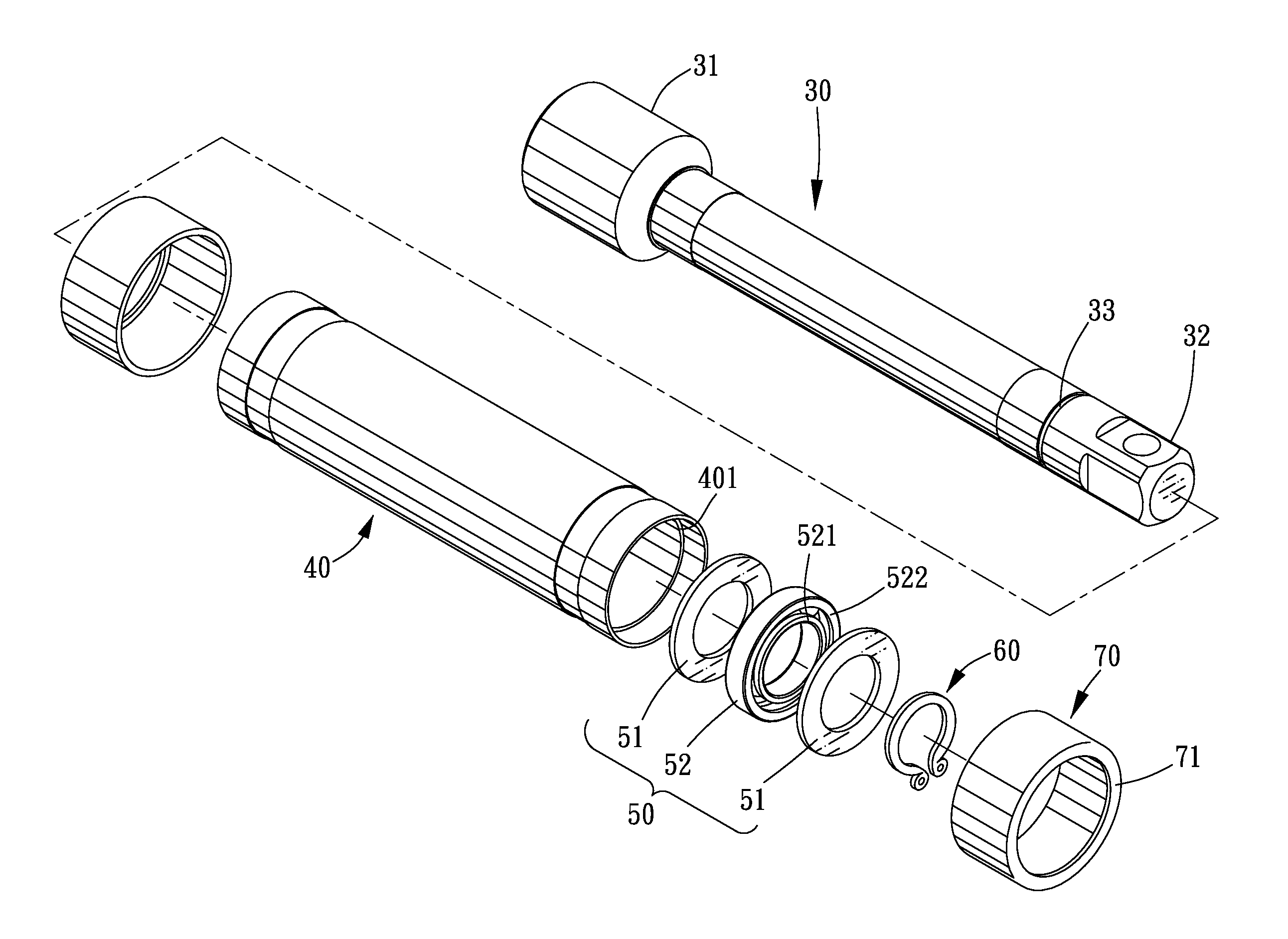
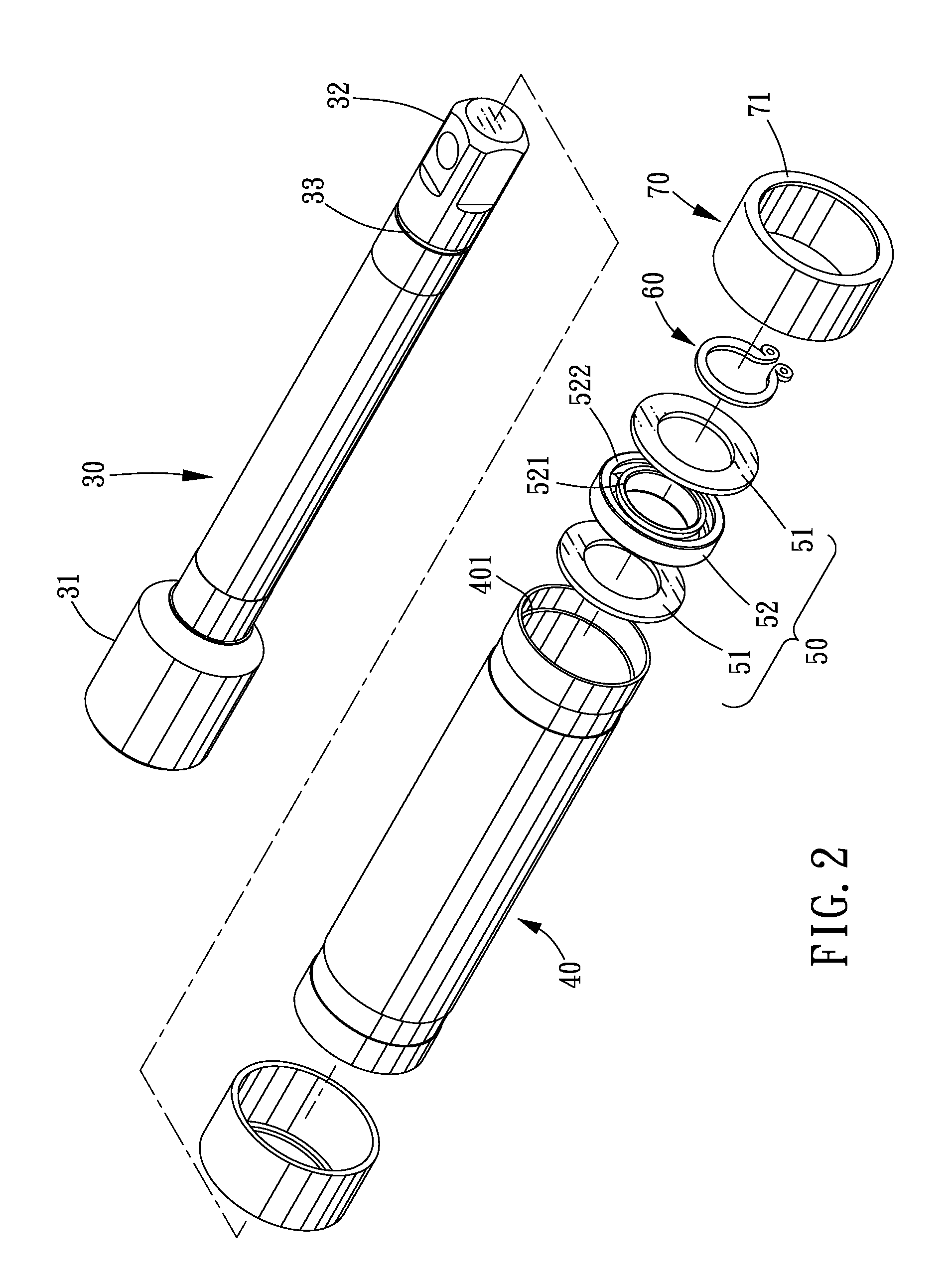
[0021]Referring to FIGS. 2-5, a connecting rod with a handle in accordance with a preferred embodiment of the present invention comprises a connecting rod 30, a handle 40, two bearing assemblies 50, a fastener 60, and two protecting covers 70.

[0022]The connecting rod 30 includes a first connecting end 31 and a second connecting end 32. The first connecting end 31 is formed with a rectangular groove, and the second connecting end 32 is configured in the form of a rectangular cylinder. The connecting rod 30 is formed in an outer periphery thereof with an annular groove 33 adjacent to the second connecting end 32.

[0023]The handle 40 is in the form of a pipe and engaged between the first connecting end 31 and the second connecting end 32 of the conne...


PUM

PropertyMeasurementUnit
inner diameteraaaaaaaaaa
outer diameteraaaaaaaaaa
speedaaaaaaaaaa

Abstract

A connecting rod with a handle comprises a connecting rod and a handle between which two bearing assemblies are disposed to allow the connecting rod to rotate relative to the handle smoothly. At both sides of each of bearings of the respective bearing assemblies are provided two protecting plates which can protect the connecting rod against the impact, avoiding the damage to the bearings, reducing the part damage probability and extending the service life of the connecting rod.

Description

BACKGROUND OF THE INVENTION[0001]1. Field of the Invention[0002]The present invention relates to a hand tool; and more particularly to a connecting rod with a handle.[0003]2. Description of the Prior Art[0004]As shown in FIG. 1, a conventional connecting rod 10 is exteriorly provided with a handle 20. In each of two opposite ends of the connecting rod 10 is disposed a bearing 11, so that when the connecting rod 10 is driven by an electric tool to rotate at a high speed, the user can hold the handle 20, while allowing the connecting rod 10 to rotate the tool, thus improving the convenience in use. However, the respective bearings 11 are located in both ends of the handle 20, so that when the connecting rod 10 falls onto the ground accidentally or is subjected to impact, the bearings 11 in both ends of the handle 20 are likely to be damaged, which might cause unsmooth rotation or even failure of the handle 20.[0005]The present invention has arisen to mitigate and / or obviate the afore-...

Claims


Application Information

Patent Timeline
Patent Type & Authority Applications(United States)
IPC IPC(8): F16D1/00
CPCF16C35/077Y10T403/24F16C2322/50
Inventor LU, SU-LAN
Owner LU SU LAN
Why Eureka
Try Eureka