Low Viscosity Monomer for Patterning Optical Tape

a monomer and optical tape technology, applied in the field of optical tape storage technology, can solve the problems of layer damage, metal and dielectric layer thickness variation, and a number of detrimental effects, and achieve the effect of improving mechanical stability and less susceptible to electron beam damag

Inactive Publication Date: 2011-12-29
ORACLE INT CORP
View PDF5 Cites 6 Cited by
  • Summary
  • Abstract
  • Description
  • Claims
  • Application Information

AI Technical Summary

Benefits of technology

The present invention solves one or more problems of the prior art by providing, in at least one embodiment, a method for forming an optical tape for data storage from a substrate film. The method of the present embodiment includes a step of patterning a curable liquid composition onto the substrate film. The curable liquid composition comprises a free radical photoinitiator and a polymerizable component that includes at least one acrylate. The curable liquid composition coated on the substrate film is illuminated with actinic radiation to form a patterned imprint layer disposed over the substrate film. A multilayer data recording assembly is placed over the second imprint layer side to form the optical tape. Advantageously, the imprint layer formed in the present embodiment is less susceptible to electron beam damage and has improved mechanical stability as compared to the imprint layers currently used to fabricate optical tape medium.

Problems solved by technology

Moreover, optical tape usually includes optical servo marks embossed into the imprint layer along the length of the tape for operating with a servo control system for controlling the optical head, Although the current optical tape technology works reasonably well, there are a number of problems related to the polymeric imprint layer.
The imprint layers tend to cause a number of detrimental effects due to dimensional changes that occur therein.
For example, such dimensional changes may cause thickness variations in the metal and dielectric layers.
Although these effects are believed to be due to poor mechanical and thermal properties of the imprint polymer, it is also thought that the sensitivity of the imprint layer to electron beam damage during the metal layer and dielectric layer depositions also contributes to these changes.

Method used


Image

  • Low Viscosity Monomer for Patterning Optical Tape
  • Low Viscosity Monomer for Patterning Optical Tape
  • Low Viscosity Monomer for Patterning Optical Tape

Examples


Embodiment Construction

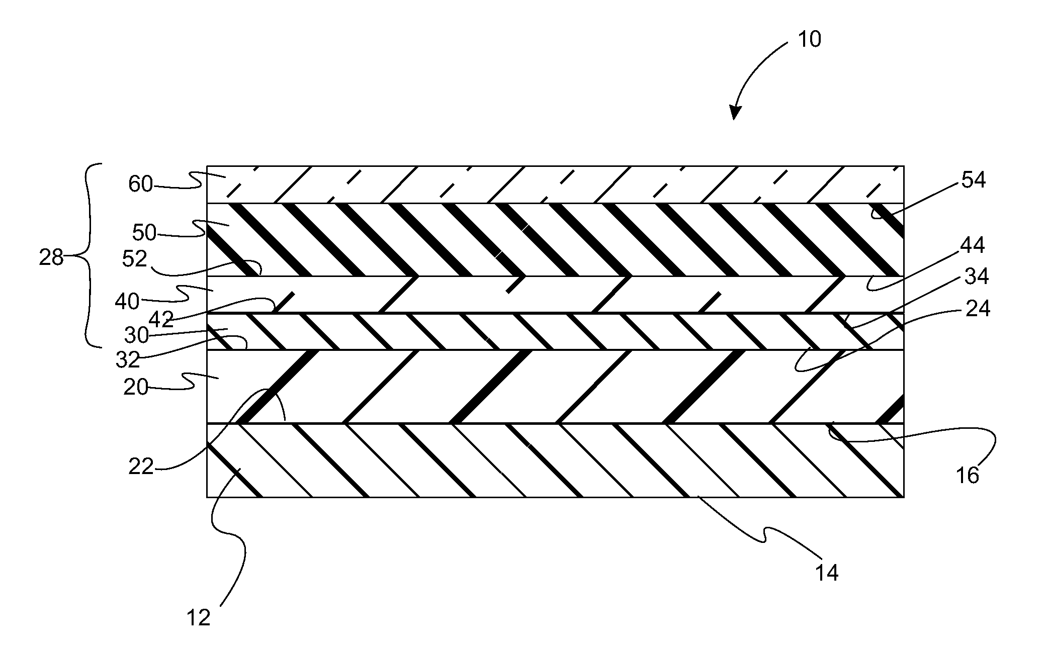
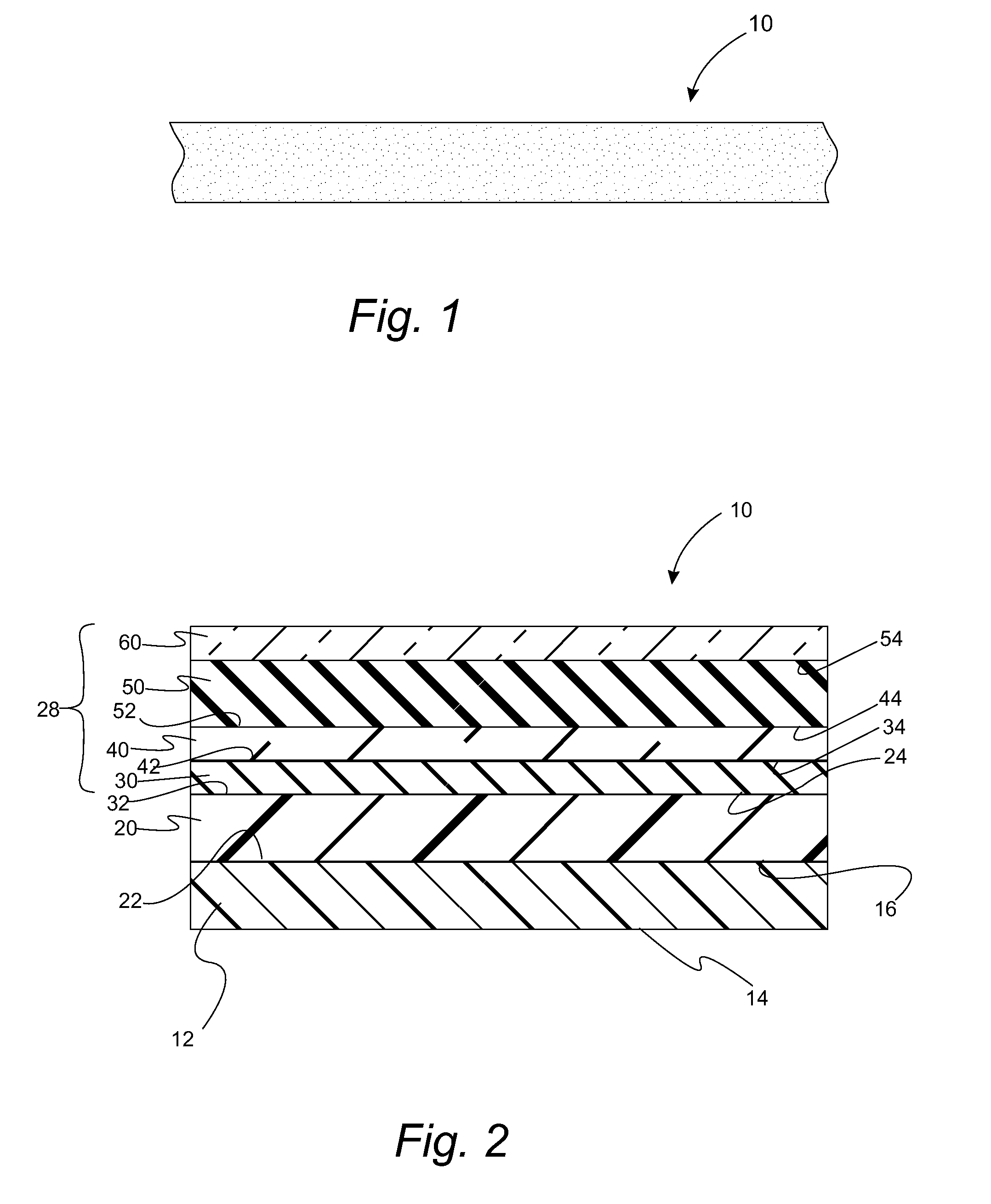
Reference will now be made in detail to presently preferred compositions, embodiments and methods of the present invention, which constitute the best modes of practicing the invention presently known to the inventors. The Figures are not necessarily to scale. However, it is to be understood that the disclosed embodiments are merely exemplary of the invention that may be embodied in various and alternative forms. Therefore, specific details disclosed herein are not to be interpreted as limiting, but merely as a representative basis for any aspect of the invention and / or as a representative basis for teaching one skilled in the art to variously employ the present invention.

Except in the examples, or where otherwise expressly indicated, all numerical quantities in this description indicating amounts of material or conditions of reaction and / or use are to be understood as modified by the word “about” in describing the broadest scope of the invention. Practice within the numerical limits...


PUM

PropertyMeasurementUnit
thicknessaaaaaaaaaa
thicknessaaaaaaaaaa
thicknessaaaaaaaaaa

Abstract

A method for forming an optical tape for data storage from a substrate film includes a step of patterning a curable liquid composition onto a side of the substrate film. Characteristically, the curable liquid composition includes a free radical photoinitiator and a polymerizable component that includes at least one acrylate. The curable liquid composition is illuminated with actinic radiation to form a patterned imprint layer disposed over the substrate film. A multilayer data recording assembly is placed over the imprint layer. An optical tape made by the method is also provided.

Description

BACKGROUND1. FieldThe present invention relates to optical tape storage technology and in particular to methods for making optical tape.2. Description of the Related ArtThe ever expanding amount of digital data provides an impetus for the continuing development of high capacity storage solutions. Technologies that are suitable for these applications include optical tape, magnetic tape, and optical disks. Of these possibilities, optical tape technology is believed to provide the greater storage capacity.The typical optical tape medium includes a base film such as polyethylene naphthalate (PEN) over-coated with multiple layers for recording digital data. A polymeric imprint layer is usually disposed over the base film. In one type of optical tape, the imprint layer is over-coated with a reflective metallic layer that is, in turn, over-coated with a sequence of dielectric layer, phase change layer, and dielectric layer. The actual data recording and reading occurs in the phase change l...

Claims


Application Information

Patent Timeline
Patent Type & Authority Applications(United States)
IPC IPC(8): B05D3/06B32B3/00C23C14/34G11B7/24G11B7/24009G11B7/243G11B7/2433G11B7/2548G11B7/257
CPCG11B7/24009G11B7/245Y10T428/24479G11B7/263G11B7/252
Inventor KIM, EUI KYOON
Owner ORACLE INT CORP
Why Eureka
Try Eureka