
Drill presses having laser alignment systems and methods therefor

a technology of laser alignment and drill presses, which is applied in the field of drill presses, can solve the problems of difficult alignment adjustments, complicated and time-consuming procedures, and low precision of selected hole locations

Active Publication Date: 2011-12-29
CHANG TYPE INDAL
View PDF8 Cites 17 Cited by
  • Summary
  • Abstract
  • Description
  • Claims
  • Application Information

AI Technical Summary

Benefits of technology

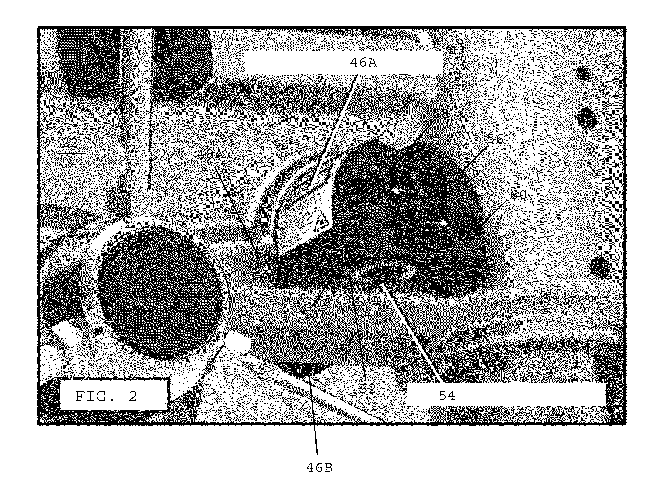
[0013]In one embodiment, the base preferably includes a first rotation flange and the rotatable element includes a second rotation flange. The rotation adjusting mechanism desirably couples the first and second rotation flanges together for selectively changing spacing between the first and second rotation flanges for rotating the rotatable element relative to the base. In one embodiment, the laser preferably rotates within the laser aperture of the base during rotation of the rotatable element. In one embodiment, the second rotation flange has an elongated opening extending in a substantially horizontal direction that enables the rotation adjusting mechanism to slide freely within the elongated opening during rotation of the rotatable element relative to said base.
[0014]In one embodiment, the pivotable element preferably includes a first pivot flange and the rotatable element preferably has a second pivot flange, whereby the pivot adjusting mechanism couples the first and second pivot flanges together for selectively changing spacing between the first and second pivot flanges for pivoting the pivotable element relative to the base. In one embodiment, the laser desirably pivots within the laser aperture of the base during pivoting of the pivotable element. In one embodiment, the first pivot flange has an elongated slot extending in a substantially vertical direction that enables the pivot adjusting mechanism to slide freely within the elongated opening of the first pivot flange during pivoting of the pivotable element relative to said base.
[0019]In one embodiment, the pivotable element preferably has a tubular element with an upper end, a lower end, and an axial opening extending between the upper and lower ends thereof. In one embodiment, the laser is desirably received within the axial opening of the tubular element. The tubular element preferably has a pair of pivot pins projecting outwardly from opposite sides thereof that are adapted to be seated within a central opening of the rotatable element for enabling the pivotable element to pivot relative to the rotatable element. In one embodiment, the tubular element preferably has a set screw coupled therewith for securing the laser to the tubular element. The set screw is preferably accessible at an outer surface of the tubular element.

Problems solved by technology

The procedure is complicated and time-consuming, and the selected hole location frequently does not have a high level of precision.
One drawback associated with conventional laser devices is that alignment adjustments are difficult to make.
One extraneous movement may misalign the laser, thereby requiring the user to re-start the alignment process.
In addition, with conventional laser alignment devices, as the locking screw is tightened, the locking screw often causes the laser to move out of alignment.
This is the source of great frustration for operators, which often causes operators to overcompensate for the misalignment that will occur when tightening the locking screw.

Method used


Image

  • Drill presses having laser alignment systems and methods therefor
  • Drill presses having laser alignment systems and methods therefor
  • Drill presses having laser alignment systems and methods therefor

Examples


Embodiment Construction

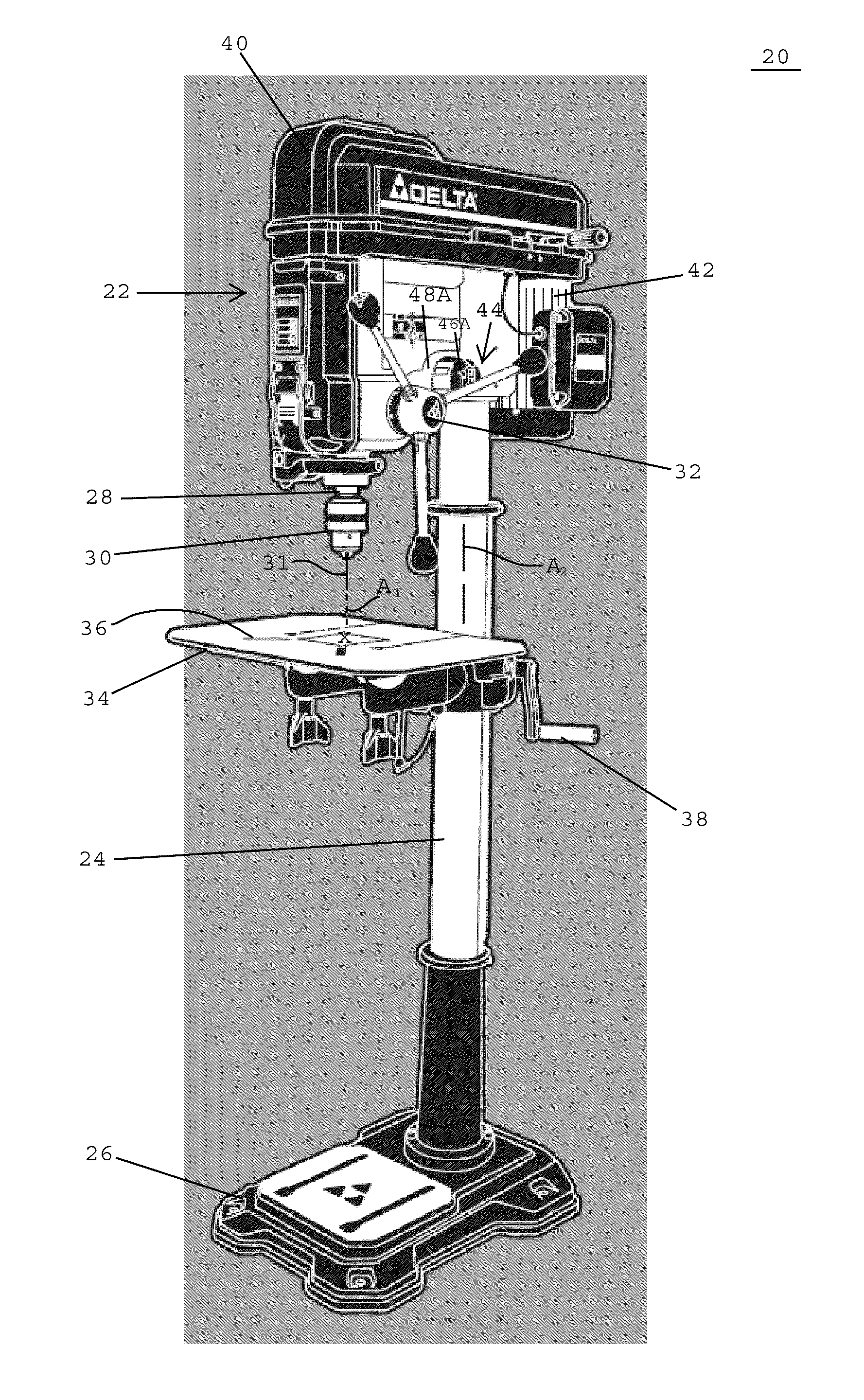
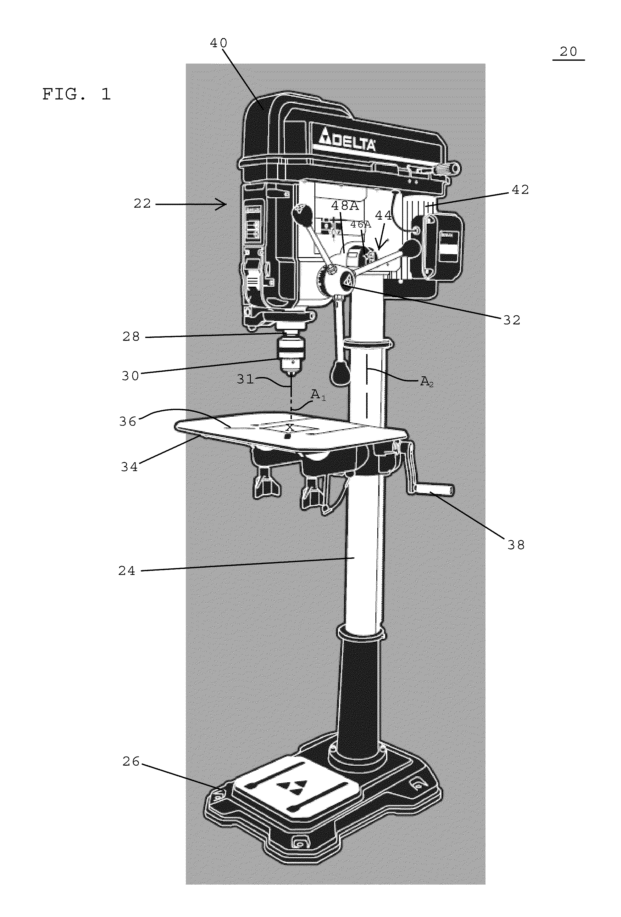
[0039]Referring to an exemplary embodiment illustrated in FIG. 1, a drill press 20 for drilling holes in work pieces preferably includes a head stock 22 supported atop a vertically-extending support column 24 and a stand 26 supporting a lower end of the support column. The drill press 20 desirably includes a rotatable spindle 28 projecting from a lower end of the head stock 22 and a chuck 30 mountable to a lower end of the spindle. The chuck 30 is preferably adapted to receive a drill bit 31 used for drilling holes in work pieces. The drill press desirably includes a rotatable handle 32 that may be engaged by an operator for lowering the rotatable spindle 28, the chuck 30, and the drill bit 31 along a vertical axis A1 that is parallel with the vertically-extending, longitudinal axis A2 of the support column 24. The drill press 20 also preferably includes a table 34 having a top surface 36 adapted to support work pieces below the spindle 28, the chuck 30, and the drill bit 31. The dr...


PUM

PropertyMeasurementUnit
Angleaaaaaaaaaa

Abstract

A laser alignment system for a drill press includes first and second adjustable laser assemblies mountable on the drill press. Each adjustable laser assembly includes a base firmly affixed to the drill press, a rotatable element mounted on the base and being adapted to selectively rotate relative to the base, a pivotable element mounted on the rotatable element and being adapted to selectively pivot relative to the rotatable element, and a laser mounted on the pivotable element and being adapted to move simultaneously with the pivotable element. The laser alignment system includes a pivot adjusting mechanism coupled with the pivotable element for selectively pivoting the pivotable element relative to the rotatable element, and a rotation adjusting mechanism coupled with the rotatable element for selectively rotating the rotatable element relative to the base.

Description

BACKGROUND OF THE INVENTION[0001]1. Field of the Invention[0002]The present invention is generally related to drill presses and is more specifically related to alignment devices for drill presses.[0003]2. Description of the Related Art[0004]Before using a conventional drilling machine, an operator will draw lines on a work piece to mark the location where a hole will be drilled. The operator must then use a relatively small drill bit to form an impression on the work piece to check whether the drill bit hits the impression at the marked location. When the impression and the marked location are matched, a selected drill bit is installed in the chuck of the drilling machine and aimed at the impression on the work piece. The drilling machine may then be operated to drill the desired hole in the work piece. The above-described process normally takes several attempts to properly align the drill bit with the selected hole location. The procedure is complicated and time-consuming, and the ...

Claims


Application Information

Patent Timeline
IPC IPC(8): B23B49/00G01B11/27
CPCB23Q17/2423B25H1/0092Y10T408/21
Inventor MONTPLAISIR, SARAH JANEGOLDMAN, DAVID ANDREW
Owner CHANG TYPE INDAL
Learn More