
Digital camera and interchangeable lens unit

a digital camera and lens unit technology, applied in the field of lenses interchangeable digital cameras and interchangeable lens units, can solve the problems of difficult expansion of an area of a ground pattern of a circuit board, increased interference, and increased interference by unwanted radiation noise, so as to reduce unwanted radiation noise

Inactive Publication Date: 2011-12-29
PANASONIC CORP
View PDF4 Cites 40 Cited by
  • Summary
  • Abstract
  • Description
  • Claims
  • Application Information

AI Technical Summary

Benefits of technology

[0010]With this configuration, the ground pattern of the circuit board installed with the electronic circuit device and the ground terminal of the connection terminal are electrically grounded on the metal portion of the lens mount through the ground connection section and the extended wiring pattern which are provided in the wiring member, and hence a ground potential in the electronic circuit device of the interchangeable lens unit can be brought into a stable state, thereby to reduce unwanted radiation noise based on the instability of the ground potential.

Problems solved by technology

As thus described, in the lens interchangeable digital camera, although the electronic circuit device mounted on the ring-shaped circuit board is installed in the cylindrical lens barrel of the interchangeable lens unit, since the circuit board is formed in the ring shape and thus has a small area, it is difficult to expand an area of a ground pattern of the circuit board.
As a result, a ground potential of the electronic circuit device becomes unstable, thereby causing a problem of an influence exerted by an unwanted radiation noise from the electronic circuit device.
As a result, the influence exerted by the unwanted radiation noise becomes more problematic.

Method used


Image

  • Digital camera and interchangeable lens unit
  • Digital camera and interchangeable lens unit
  • Digital camera and interchangeable lens unit

Examples


Embodiment Construction

[0021]Hereinafter, a digital camera and an interchangeable lens unit according to an embodiment of the present invention are described with reference to the drawings.

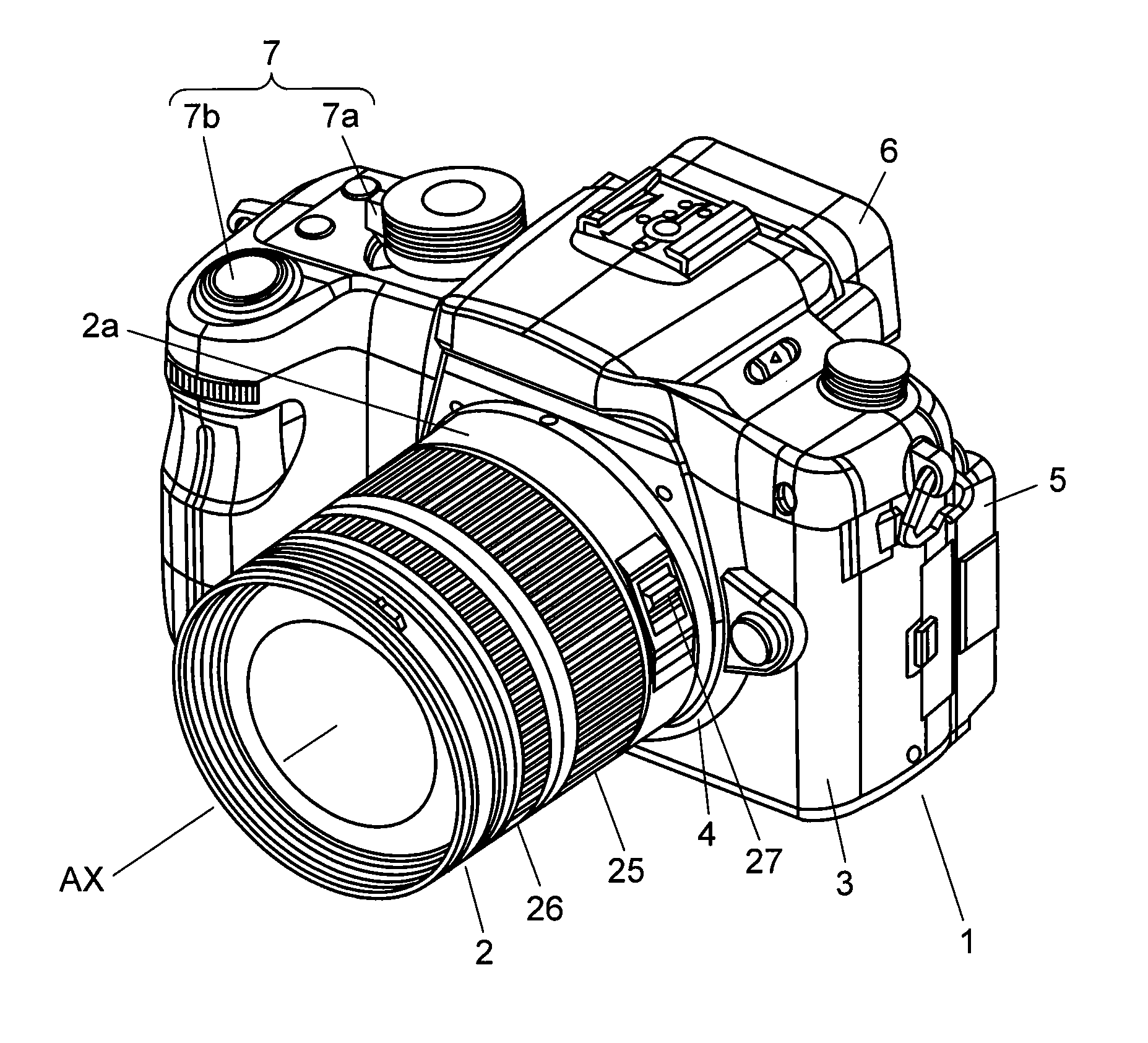
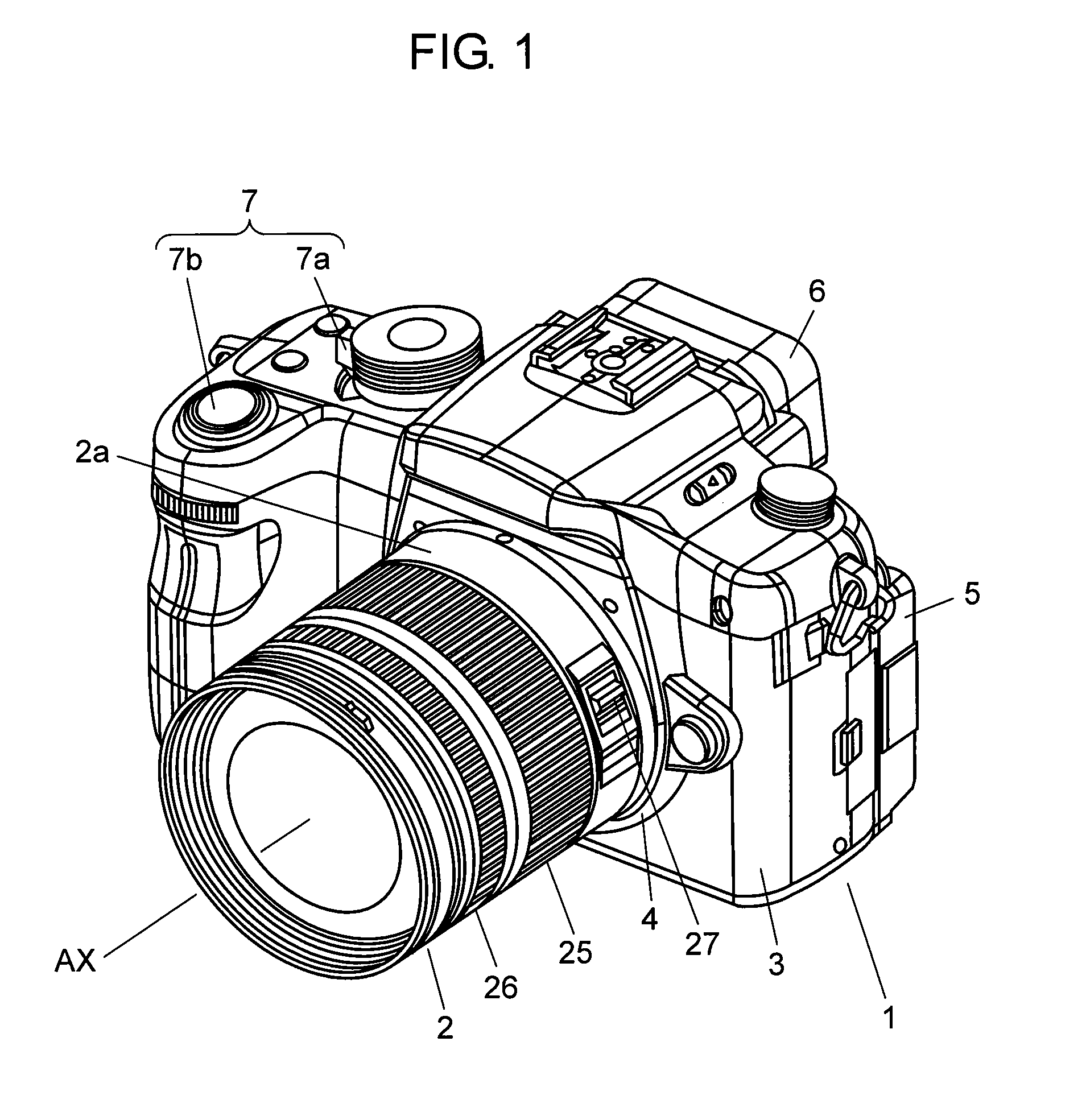
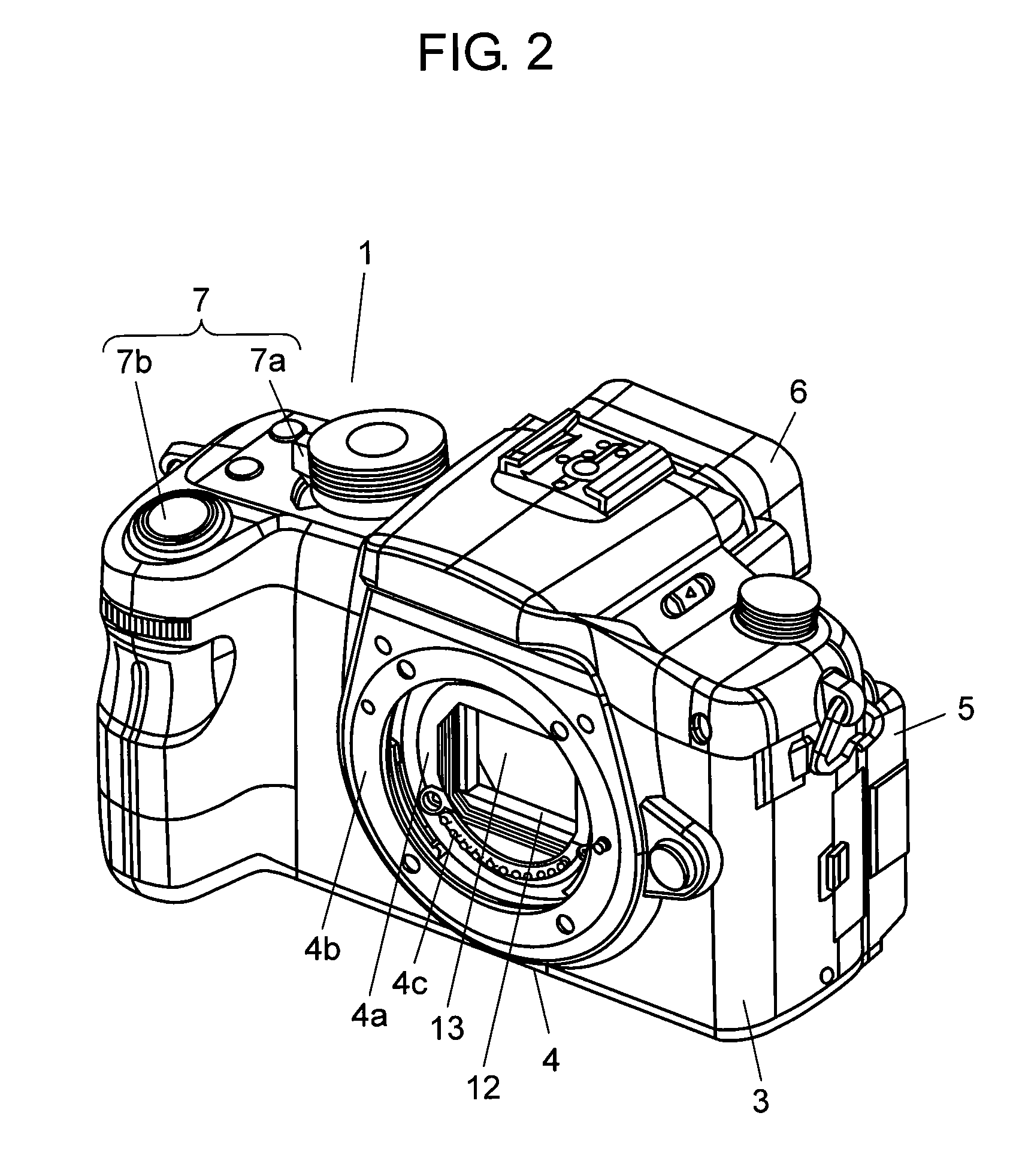
[0022]FIG. 1 is a perspective view showing an external view of a digital camera according to an embodiment of the present invention, FIG. 2 is a perspective view showing a camera body with an interchangeable lens unit removed therefrom, FIG. 3 is a schematic sectional view of the digital camera, and FIG. 4 is a function block diagram of the digital camera.

[0023]As shown in FIGS. 1 to 4, the digital camera according to the present invention is provided with camera body 1 and interchangeable lens unit 2 which is mountable on camera body 1.

[0024]Camera body 1 is provided with: body housing 3; body mount 4 which is arranged on the front face side of this body housing 3 and on which interchangeable lens unit 2 is mountable; camera monitor 5 arranged on the back face side of body housing 3 and made up of a liquid crystal disp...


PUM


Abstract

A circuit board is arranged on an end face of a lens barrel on a lens mount side and installed with an electronic circuit device, a plurality of connection terminals which are arranged in an electrically insulating state in the lens mount and serve to connect the electronic circuit device on the circuit board with an electronic circuit device inside a camera body, and a wiring member is for connecting the plurality of connection terminals with the circuit board, where the wiring member is provided with a ground connection section which is connected to a ground pattern of the circuit board and also electrically connected to a connection terminal that is to be a ground terminal among the plurality of connection terminals, and an extended wiring pattern is for electrically grounding the ground connection section on a metal portion of the lens mount.

Description

TECHNICAL FIELD[0001]The present invention relates to a lens interchangeable digital camera and an interchangeable lens unit.BACKGROUND ART[0002]A digital camera has a configuration where a picked-up photographed image is converted to image data of a digital signal by use of an imaging device such as an image sensor, and the data is recorded in a recording medium such as a built-in memory or a memory card. Further, among digital cameras, there is a lens interchangeable digital camera called a single-lens digital camera, with such a configuration where a variety of lenses are interchangeable according to user's preferences.[0003]In this lens interchangeable digital camera, since a lens is arranged in a central section of a cylindrical lens barrel of an interchangeable lens unit, an electronic circuit device for controlling movement of the lens and the like has a structure of being mounted on a circuit board in a ring shape or in a shape like a partially missing ring shape.[0004]As th...

Claims


Application Information

Patent Timeline
IPC IPC(8): H04N5/225G03B17/00
CPCG02B7/02H04N5/23209H04N5/2254G03B17/14H04N23/663
Inventor FUJINO, SHINKUROFUSAYASU, HIROTSUGUMIMURA, SHOUICHIKUMOI, MASAFUMITOBINAGA, MASATOAOYAMA, AKIHIROWADA, YASUHIRO
Owner PANASONIC CORP
Learn More