
Linear hollow spool valve

Inactive Publication Date: 2011-12-29
GENERAL ELECTRIC CO
View PDF4 Cites 4 Cited by
  • Summary
  • Abstract
  • Description
  • Claims
  • Application Information

AI Technical Summary

Benefits of technology

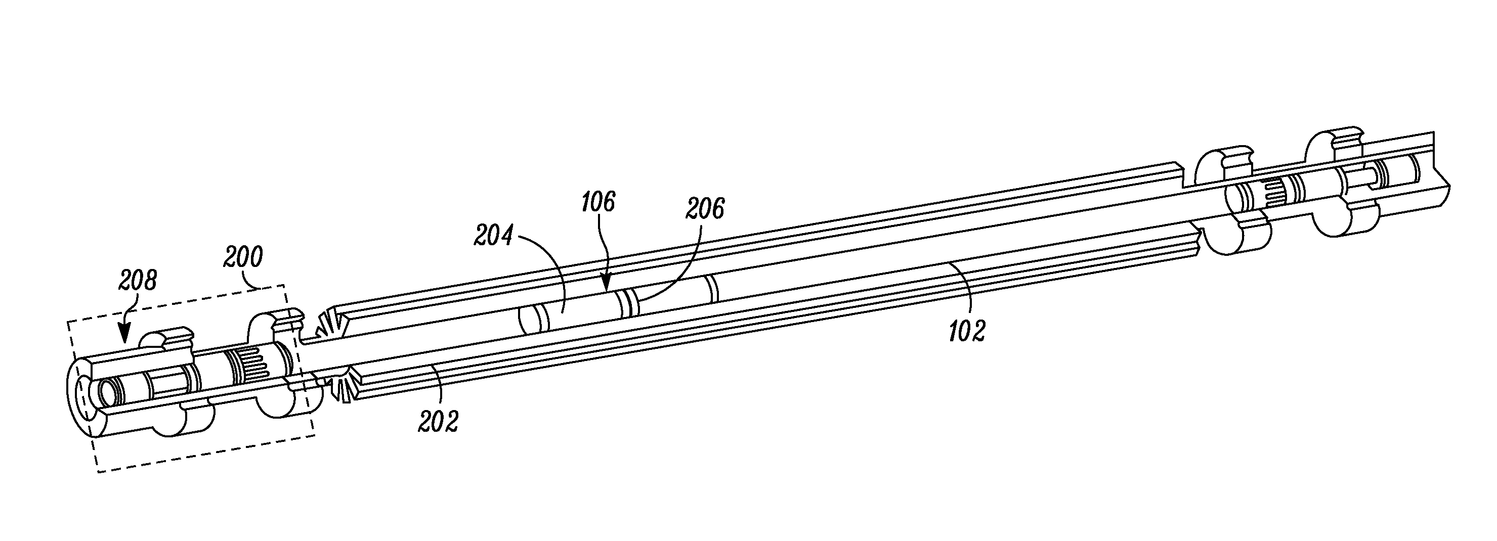
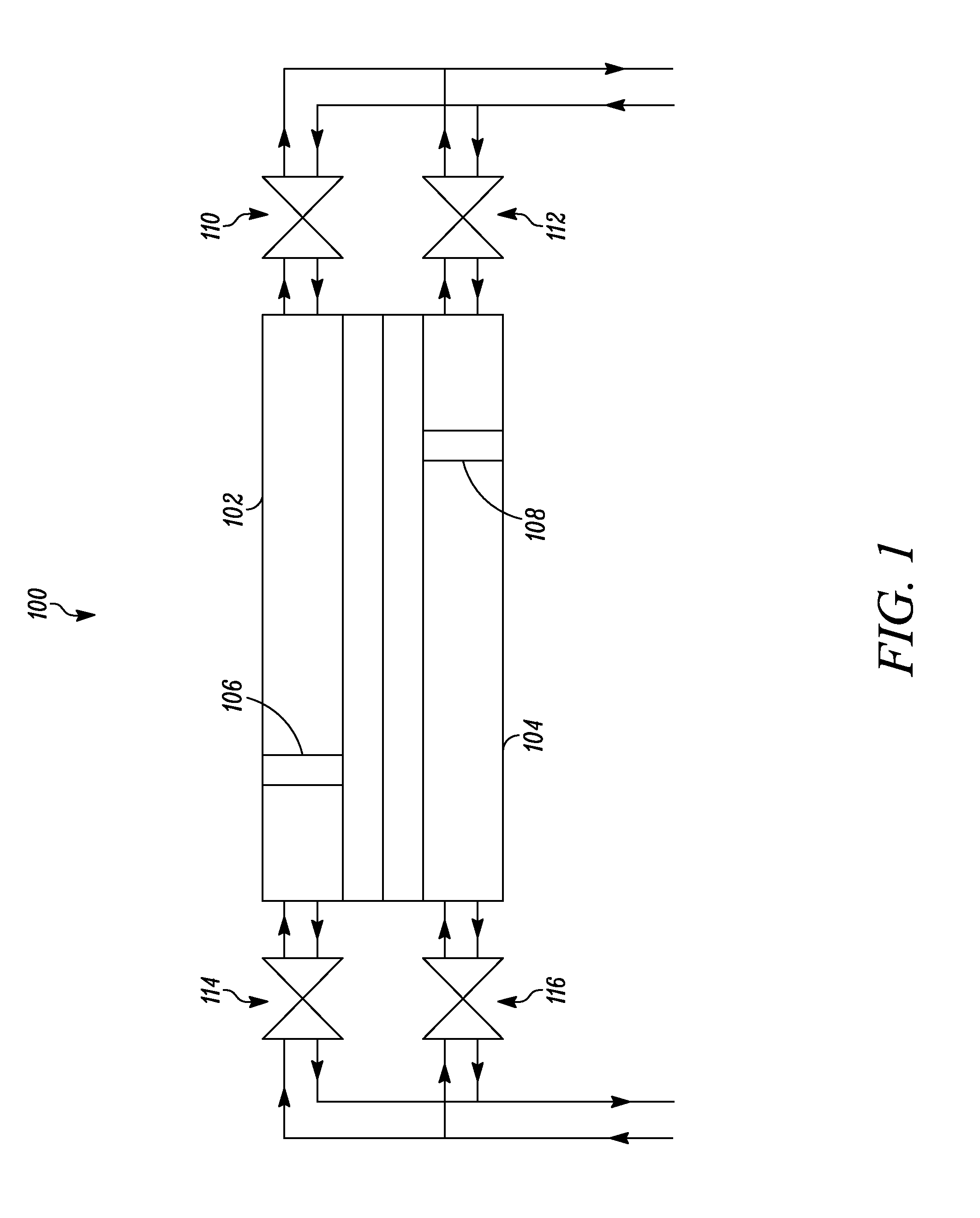
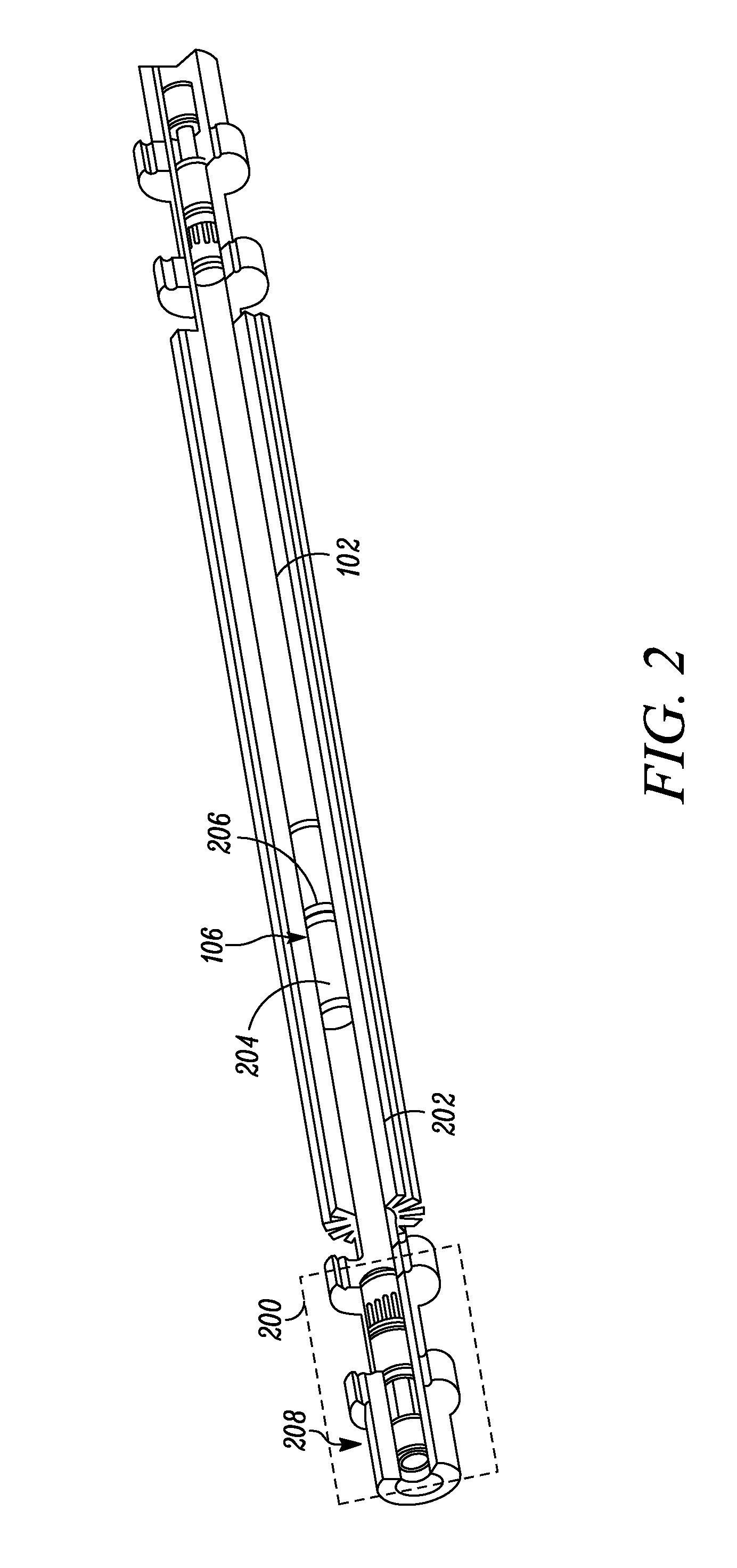
[0009]According to an aspect of the present invention, the valve system includes a valve housing, a flow distributor, a hollow spool and a sealing system. The valve housing may comprise a set of high-pressure ports and a set of low-pressure ports. The flow distributor allows the flow to and from the set of high-pressure ports and low-pressure ports within the valve housing. The hollow spool may be configured to reciprocate axially in a radial clearance between the valve housing and the flow distributor. The hollow spool may connect the pressure exchanger tube in fluid communication with the high-pressure ports or the low-pressure ports. The sealing system may be configured to provide substantial hydraulic balance to the hollow spool. Due to the axial hydraulic balance, lower actuation force may be required for controlling the movement of the hollow spool. Accordingly, the low actuation force may permit the use of an externally driven hollow spool which overcomes previous challenges with the actuators that penetrate the pressure exchanger tubes or the valve body.

Problems solved by technology

Such valve systems are usually complicated, heavy, expensive, and more susceptible to failure.
Moreover, independent operation of the pressure exchanger tubes may not be possible.
Some of these hydraulic loads may be unbalanced and may oppose an applied actuating load.
This may increase the cost of actuating the valve system and may also reduce the efficiency of the energy recovery system.
Also, unbalanced loads may reduce the overall life of the sealing system.
This may increase the cost and complexity of the energy recovery system.
The sealing system themselves may be vulnerable to leakage.

Method used


Image

  • Linear hollow spool valve
  • Linear hollow spool valve
  • Linear hollow spool valve

Examples


Embodiment Construction

[0016]Various embodiments of the present invention will be described in detail below with reference to the accompanying drawings. It will be apparent, however, that these embodiments may be practiced without some or all of these specific details. In other instances, well known process steps or elements have not been described in detail in order to not to unnecessarily obscure the description of the invention. The following example embodiments and their aspects are described and illustrated in conjunction with apparatuses, methods, and systems which are meant to be illustrative examples, not limiting in scope.

[0017]The invention provides a valve system for pressure exchanger tubes of an energy recovery system. The energy recovery system is a device that utilizes a waste stream of a sub-system to minimize the input of energy to the whole system by exchange of energy from one sub-system to another. In desalination systems, the energy recovery system may be utilized to transfer the pres...


PUM


Abstract

A valve system for pressure exchanger tubes of an energy recovery system is provided. The valve system includes a valve housing, a flow distributor, a hollow spool and a sealing system. The valve housing may comprise a set of high-pressure ports and a set of low-pressure ports. The flow distributor allows the flow to and from the set of high-pressure ports and the set of low-pressure ports within the valve housing. The hollow spool may be configured to reciprocate axially in a radial clearance between the valve housing and the flow distributor. The hollow spool may connect the pressure exchanger tube in fluid communication with the high-pressure ports or the low-pressure ports. The sealing system may be provided within the valve housing for imparting substantial hydraulic balance to the hollow spool.

Description

BACKGROUND[0001]Embodiments of the present invention relate to an energy recovery system. More particularly, the embodiments of the present invention relate to a valve system for the energy recovery system.[0002]An energy recovery system is a device that utilizes a fluid stream at a higher pressure to pressurize another fluid at a lower pressure. Energy recovery systems are generally used in desalination plants to pressurize a feed stream by using high pressure concentrate.[0003]An energy recovery system may include a pressure exchanger tube and a piston reciprocating inside the pressure exchanger tube. Further, a valve system may control the flow of feed water into the pressure exchanger tube and the concentrate out of the pressure exchanger tube. One form of the energy recovery system may include two or more pressure exchanger tubes. Various valve systems are known in the art, for example, rotary valve systems and linear valve systems.[0004]Valve systems are generally connected to...

Claims


Application Information

Patent Timeline
IPC IPC(8): F16K11/07
CPCF16K11/0716Y10T137/8671F16K11/07F16K31/122
Inventor ANDERSON, TODD ALANSHAH, MANOJ RAMPRASADBEAUCHAMP, PHILIP PAULKALLURI, RAMMOHAN RAOBHAT, SUMA MEMANA NARAYANAKOMMEPALLI, HAREESH KUMAR REDDY
Owner GENERAL ELECTRIC CO
Learn More