
Electrode array having embedded electrodes and methods of making the same

a technology of electrode array and electrode array, which is applied in the field of brain stimulation devices and methods, can solve the problems of increased time for the proper therapeutic effect to be obtained, unwanted stimulation of neighboring neural tissue, undesired side effects,

Active Publication Date: 2011-12-22
BOSTON SCI NEUROMODULATION CORP
View PDF4 Cites 352 Cited by
  • Summary
  • Abstract
  • Description
  • Claims
  • Application Information

AI Technical Summary

Problems solved by technology

This results in the unwanted stimulation of neighboring neural tissue, undesired side effects and an increased duration of time for the proper therapeutic effect to be obtained.

Method used


Image

  • Electrode array having embedded electrodes and methods of making the same
  • Electrode array having embedded electrodes and methods of making the same
  • Electrode array having embedded electrodes and methods of making the same

Examples


second embodiment

[0064]FIG. 3B is a schematic perspective view of a pre-electrode 300. The pre-electrode 300 of FIG. 3B includes fixing lumens 330 and conductor lumens 320. The pre-electrode 300 also includes a divider 310 with four partitioning arms. As previously noted, a divider 310 may include any number of partitioning arms such as three, four, five, six, eight, ten, or twelve portioning arms. Thus, a single pre-electrode 300 may be used to form four segmented electrodes. As can be seen in FIG. 3B, the pre-electrode 300 is formed in the shape of a cube. The cube-shaped pre-electrode 300 may be further processed to form segmented electrodes having the desired shape and size.

[0065]FIG. 4 is a schematic perspective view of one embodiment of a segmented electrode 400. The segmented electrode 400 may be the result of partitioning the pre-electrode 300 of FIG. 3A along divider 310. In some embodiments, after partitioning the pre-electrode 300, each segmented electrode 400 includes a single fixing lum...

third embodiment

[0072]FIGS. 6B and 6C are schematic perspective views of a second and third embodiment of an electrode frame 610. As seen in FIGS. 6B and 6C, the electrode frames 610 may include various electrode chambers 620 with a variety of different shapes. For example, the electrode frames 610 may be formed to house different-shaped segmented electrodes. As seen in FIG. 6C, in some embodiments, the electrode frame 610 lacks an opening 636, but is formed slightly larger in diameter so as to be press fit over the lead body.

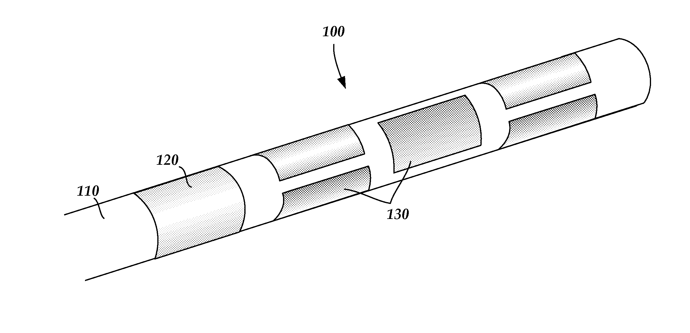
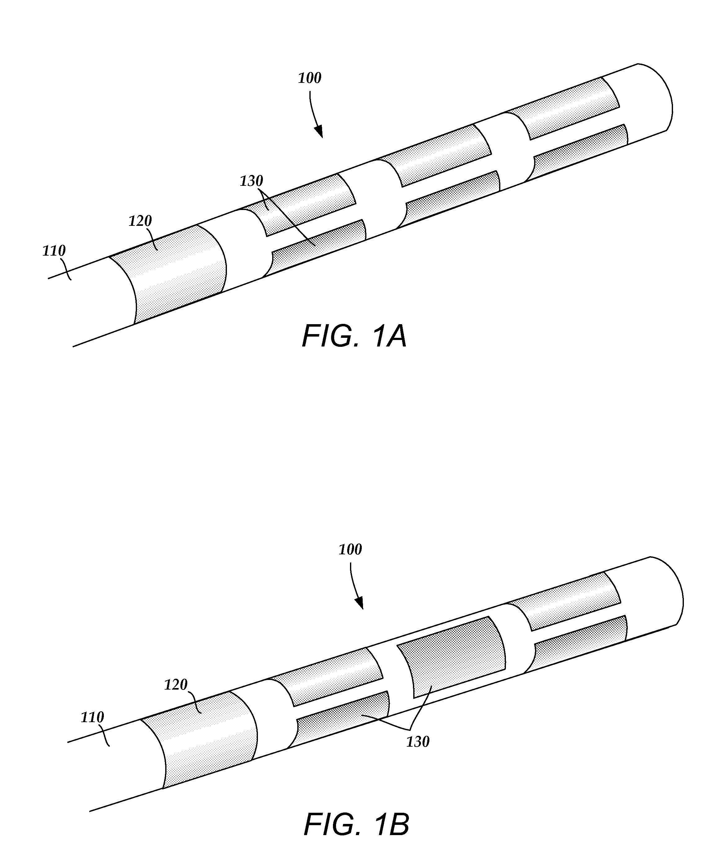
[0073]The segmented electrodes 710 may be formed of platinum, platinum-iridium, iridium, 316L stainless steel, tantalum, nitinol, a conductive polymer, or any other suitable conductive material. FIG. 7A is a schematic perspective view of one embodiment of a segmented electrode 710 corresponding to the electrode frame 610 of FIG. 6A, formed of an elongate member with an arched cross-section. FIG. 7B is a schematic perspective view of a second embodiment of a segmented electrode...


PUM

PropertyMeasurementUnit
diameteraaaaaaaaaa
diameteraaaaaaaaaa
lengthaaaaaaaaaa

Abstract

A method of manufacturing a device for brain stimulation includes forming a lead body having a distal end section and coupling at least one pre-electrode to the distal end section of the lead body. The pre-electrode defines a divider with a plurality of partitioning arms, and has a plurality of fixing lumens. A portion of the pre-electrode aligned with the portioning arms is removed to divide the pre-electrode into a plurality of segmented electrodes. Each of the plurality of segmented electrodes defines at least one of the plurality of fixing lumens at least partially disposed through the segmented electrode. A material is introduced through the at least one fixing lumen to couple the plurality of segmented electrodes to the lead body.

Description

CROSS-REFERENCE TO RELATED APPLICATIONS[0001]This application claims the benefit under 35 U.S.C. §119(e) of U.S. Provisional Patent Application Ser. No. 61 / 356,529 filed on Jun. 18, 2010, which is incorporated herein by reference.FIELD[0002]The invention is directed to devices and methods for brain stimulation including deep brain stimulation. In addition, the invention is directed to devices and method for brain stimulation using a lead having embedded segmented electrodesBACKGROUND[0003]Deep brain stimulation can be useful for treating a variety of conditions including, for example, Parkinson's disease, dystonia, essential tremor, chronic pain, Huntington's Disease, levodopa-induced dyskinesias and rigidity, bradykinesia, epilepsy and seizures, eating disorders, and mood disorders. Typically, a lead with a stimulating electrode at or near a tip of the lead provides the stimulation to target neurons in the brain. Magnetic resonance imaging (MRI) or computerized tomography (CT) scan...

Claims


Application Information

Patent Timeline
Patent Type & Authority Applications(United States)
IPC IPC(8): A61N1/05H05K13/00
CPCY10T29/49117A61N1/0534
Inventor BARKER, JOHN MICHAELPANDIT, ADITYA VASUDEOPIANCA, ANNE MARGARET
Owner BOSTON SCI NEUROMODULATION CORP
Learn More