
Rehabilitation Robot

a robot and rehabilitation technology, applied in the field of rehabilitation robots, can solve the problems of high risk of damage to joints, no control over the position of the arm during exercises, and loss of mobility of the upper limbs as that of the lower limbs

Inactive Publication Date: 2011-12-22
DEHEZ BRUNO MARC FLORENT VICTORE +3
View PDF21 Cites 51 Cited by
  • Summary
  • Abstract
  • Description
  • Claims
  • Application Information

AI Technical Summary

Benefits of technology

The invention is a device for mobilizing and rehabilitating a patient's upper limb, which is made up of several modules that can be secured to the patient's arm, forearm, elbow, wrist, and hand. The modules are designed to be easily assembled and unlocked using a pull in a direction opposite to the direction of engagement. The device can be adjusted to fit different patients and can be used for mobility and rehabilitation purposes. The technical effects of the invention include improved mobility and rehabilitation for patients with upper limb injuries or disabilities.

Problems solved by technology

Among the motor problems caused by hemiplegia, the loss of mobility of the upper limbs is just as troublesome as that of the lower limbs.
However, because the device mobilizes only the patient's hand, no control over the position of the arm is provided during the exercises.
This results in a high risk of damage to joints,
In such an exoskeleton, the axes of rotation of the exoskeleton and the corresponding physiological axes of rotation of the patient have to be exactly superposed because if they are not, there is a risk that the robot will exert undue force on the patients joints.
These mechanisms are heavy and complicated.
In addition, they do not guarantee that the mechanic axis of rotation defined by the axis of the two cylinders will coincide with the physiological axis of rotation of the patient.
Finally, this device does not allow movements of the wrist.
In addition, it is complicated, heavy and difficult to use.
However, there is nothing provided in this device to allow all or part of the upper limb, for example the shoulder, the elbow or the wrist, to be rehabilitated.
Although in theory it is possible to dismantle the parts of this device (see, for example, FIG. 2 and paragraph 26 of that document), such dismantling is not easy.
In addition, there is nothing provided for terminating a selected part or group of parts or connecting them with the limb.
However, creating a device that exhibits these features runs into various difficulties.
First of all, there is the problem of weight: whereas in the known exoskeletons like the one described in WO 2006 / 058442, the weight of the structure can be transferred from the distal part to the proximal part and to the fixed frame that supports it through the structure itself and its actuators, the same is not true if there is a desire to be able to select which joints are to be mobilized, for example only the distal joints.
Next, there is the problem of interconnectability: in order to be able to provide the patient with robotized assistance for absolutely any combination of his joints, the possibility of interconnecting and of combining the various components of the device becomes a matter of critical importance from an ergonomic standpoint, the standpoint of ease of use, and the standpoint of weight or of reacting the various forces of reaction,

Method used


Image

  • Rehabilitation Robot
  • Rehabilitation Robot
  • Rehabilitation Robot

Examples


Embodiment Construction

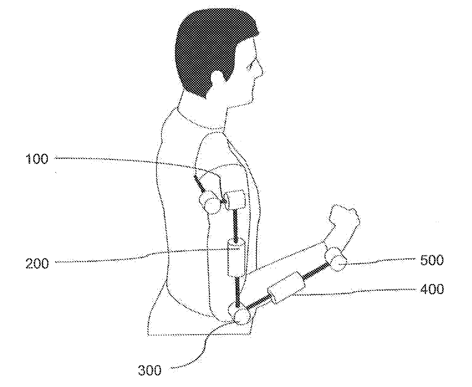
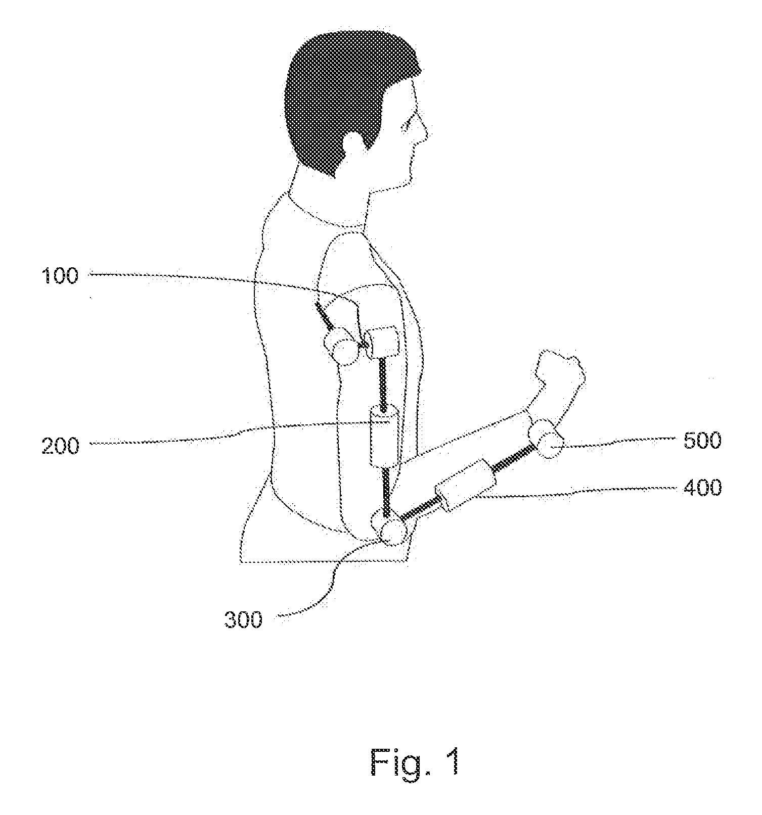
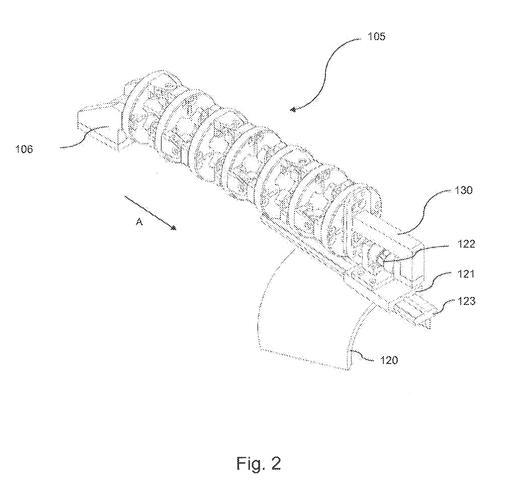
[0042]The mobilization and rehabilitation device of the invention has the overall form of an exoskeleton in as much as it is positioned along the patient's arm, in parallel with its anatomical structure. Unlike conventional exoskeletons, the structure of which deploys in one piece from the torso as far as the patient's hand, the device of the invention is made up of an assembly created from a set comprising five independent modules and three attachment accessories. The five modules take care of the movements of the three joint complexes that are the shoulder complex, the elbow complex and the wrist complex, and of the two segmental rotations that are the ulnar rotation and the humeral rotation. The three attachment accessories are a dorsal holding device, an elbow shell, and a hand shell. The shells can be created by molding, for example in reinforced polymer. A range of shells of various sizes may be produced, or shells may be custom fitted to a patient. Each of the five modules ca...


PUM

PropertyMeasurementUnit
degrees of freedomaaaaaaaaaa
angles of rotationaaaaaaaaaa
rotationaaaaaaaaaa

Abstract

The invention relates to a device for mobilizing and rehabilitating an upper limb of a patient and a method of assembling such a device, It may be made up by assembling at least two adjacent elements chosen from a set comprising a shoulder module (105) (ShouldeRO), an arm module (205) (ROThum), an elbow module (305) (elBOT), a forearm module (405) (ROTuln), a wrist module (505) (wristlC), a dorsal holding device (107), an elbow shell CC and a hand shell (514). Each of the elements (105; 205; 305; 405; 505; 107: CC; 514) of the set is designed to be secured to at least one other adjacent element (105; 205; 305; 405; 505; 107; CC; 514) of the set, at least one assembly of a first element with a second element being achievable by engaging a male piece (600) secured to the first element in a female piece (610) secured to the second element in a direction of engagement which is not subjected to any load when the device is in operation, and by locking said male piece (600) in said female piece (610) using means that can be unlocked under the effect of a pull in a direction opposite to said direction of engagement

Description

TECHNICAL FIELD[0001]The invention relates to the field of mobilization and rehabilitation robots. More specifically, the invention relates to a device for mobilizing and rehabilitating an upper limb of a patient, and to a method for assembling such a device.DESCRIPTION OF THE PRIOR ART[0002]Among the motor problems caused by hemiplegia, the loss of mobility of the upper limbs is just as troublesome as that of the lower limbs. Just think how many day-to-day actions involve both arms (getting dressed, eating, pursuing various leisure pursuits, etc). Recovery of these motor skills, which is conventionally performed by a therapist, can be hastened by the use of a robotized system as various clinical studies have already shown. However, in addition to the “robotic” performances of a given device (by which we mean: workspace, mobility, type of part, etc), there are other “higher level” criteria that need to be taken into consideration when producing such a device. These are connected wit...

Claims


Application Information

Patent Timeline
Patent Type & Authority Applications(United States)
IPC IPC(8): A61H1/02B23P11/00
CPCA61H1/0277Y10T29/49826A61H1/0285A61H2201/0107A61H2201/123A61H2201/1246A61H2201/149A61H2201/1638A61H2201/165A61H2201/1676A61H2201/5061A61H2201/5069A61H2201/5092B25J9/0006B25J18/06A61H1/0281
Inventor DEHEZ, BRUNO MARC FLORENT VICTORESAPIN, JULIEN MARIELLE DANIELDIDIER, PIERREATTANASI, ARNAUD
Owner DEHEZ BRUNO MARC FLORENT VICTORE
Learn More