
Remotely located radio transceiver for mobile communications network

a radio transceiver and mobile communication technology, applied in the direction of digital transmission, wireless commuication services, electrical equipment, etc., can solve the problem of not always being able or advisable to install the entire base station

Inactive Publication Date: 2011-12-22
UBIDYNE
View PDF7 Cites 49 Cited by
  • Summary
  • Abstract
  • Description
  • Claims
  • Application Information

AI Technical Summary

Benefits of technology

[0014]In one aspect of the teachings disclosed herein, the remotely located radio transceiver system may further comprise a frequency converter for frequency-converting the digitized signals. By performing the frequency-conversion at the remotely located radio transceiver system, the sampling rate of the digitized signals, and hence the data rate on the connection between the remotely located radio

Problems solved by technology

Due to space restrictions and accessibility restrictions at the antenna sites, it is not always possible or advisable to install the entire base station at the antenna site or close to the antenna site.

Method used


Image

  • Remotely located radio transceiver for mobile communications network
  • Remotely located radio transceiver for mobile communications network
  • Remotely located radio transceiver for mobile communications network

Examples


Embodiment Construction

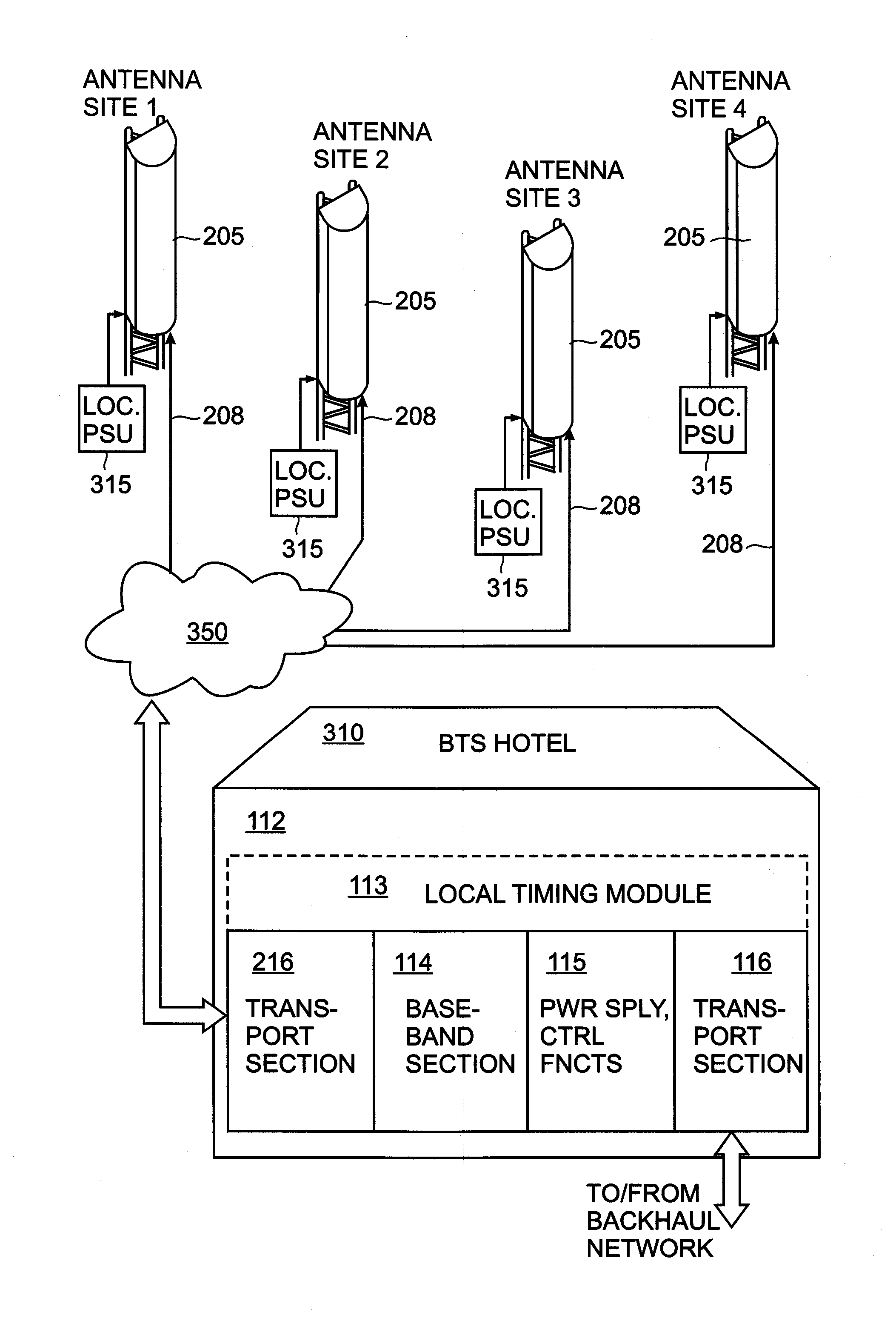
[0064]The invention will now be described on the basis of the drawings. It will be understood that the embodiments and aspects of the invention described herein are only examples and do not limit the protective scope of the claims in any way. The invention is defined by the claims and their equivalents. It will be understood that features of one aspect or embodiments of the invention can be combined with a feature of a different aspect or aspects and / or embodiments.

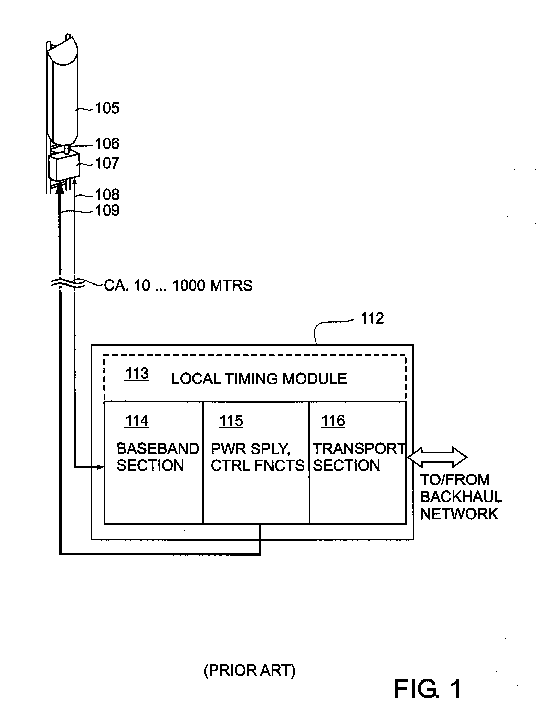
[0065]FIG. 1 shows a typical example of an existing base station architecture when utilizing a remote radio head 107. The remote radio head (RRH) 107 is connected directly to a baseband card / module 114 of a base station or a base station rack 112, typically using a fibre-optic cable 108 to transfer the high-speed digital signals which describe the carrier information to be transmitted (e.g. using OBSAI protocol or CPRI protocol). In addition to a data connection provided for by the fibre-optic cable 108, the remote radio ...


PUM


Abstract

A remotely located radio transceiver system for a mobile communications network is disclosed, comprising a radio transmitter and a radio receiver, and an asynchronous packet-based digital input / output for connecting the remotely located radio transceiver system to at least one digital processing unit. The at least one digital processing unit is adapted to provide digitised signals to, or receive digitised signals from, the remotely located radio transceiver system. A corresponding method for generating a transmit signal comprises receiving, from the at least one digital processing unit, asynchronous packet-based data at the asynchronous packet-based input / output of the remotely located radio transceiver system, and processing the asynchronous packet-based data to form the transmit signal. Another corresponding method for processing a receive signal is also disclosed.

Description

CROSS-REFERENCE TO RELATED APPLICATIONS[0001]This application is related to U.S. patent application Ser. No. ______ entitled “Mobile Communications Network with distributed Processing Resources” (Attorney's Docket No. 4424-P05086US0) filed concurrently herewith. The present application is related to U.S. patent application Ser. No. ______ entitled “Handover in Mobile Communications Network” (Attorney's Docket No. 4424-P05087US0) filed concurrently herewith. The present application is related to U.S. patent application Ser. No. ______ entitled “Remote Radio Head” (Attorney's Docket No. 4424-P05088US0) filed concurrently herewith. The entire contents of each of the foregoing applications are incorporated herein by reference.FIELD OF THE INVENTION[0002]The field of the invention relates to a remotely located radio transceiver system for a mobile communications network. The field of the invention also relates to a method for generating a transmit signal at a remotely located radio trans...

Claims


Application Information

Patent Timeline
IPC IPC(8): H04L5/16H04W8/00
CPCH04W88/085
Inventor KENINGTON, PETER
Owner UBIDYNE
Learn More