
Apparatus and method for making and assembling a multi-lens optical device

Active Publication Date: 2011-12-22
THALES VISIONIX
View PDF0 Cites 8 Cited by
  • Summary
  • Abstract
  • Description
  • Claims
  • Application Information

AI Technical Summary

Benefits of technology

[0010]In yet another respect, the invention comprises a method of designing and making a first lens for use as part of an optical device having a plurality of lenses, the first lens including a lens body having at least two optical surfaces and a perimeter edge located between the at least two optical surfaces, the method comprising: forming at least two optical surfaces of the lens body and a perimeter edge having a first perimeter shape, the first perimeter shape being a simple closed cur

Problems solved by technology

The necessity of providing precision lens housings results in an increased manufacturing cost.

Method used


Image

  • Apparatus and method for making and assembling a multi-lens optical device
  • Apparatus and method for making and assembling a multi-lens optical device
  • Apparatus and method for making and assembling a multi-lens optical device

Examples


Embodiment Construction

[0030]The ensuing detailed description provides preferred exemplary embodiments only, and is not intended to limit the scope, applicability, or configuration of the invention. Rather, the ensuing detailed description of the preferred exemplary embodiments will provide those skilled in the art with an enabling description for implementing the preferred exemplary embodiments of the invention. It being understood that various changes may be made in the function and arrangement of elements without departing from the spirit and scope of the invention, as set forth in the appended claims.

[0031]To aid in describing the invention, directional terms are used in the specification and claims to describe portions of the present invention (e.g., upper, lower, left, right, etc.). These directional definitions are merely intended to assist in describing and claiming the invention and are not intended to limit the invention in any way. In addition, reference numerals that are introduced in the spec...


PUM

PropertyMeasurementUnit
Angleaaaaaaaaaa
Shapeaaaaaaaaaa
Perimeteraaaaaaaaaa

Abstract

A system for aligning a plurality of high-precision lenses in a lens train. Each of the lenses has at least two alignment tabs disposed around the perimeter of the lens. The lenses are aligned by placing the lenses in a jig having a plurality of high-precision alignment blocks. The lenses are attached to a lower-precision shroud, having slots that receive the alignment tabs. A gap-filling adhesive is used to provide a high-precision fit for the lenses in the shroud.

Description

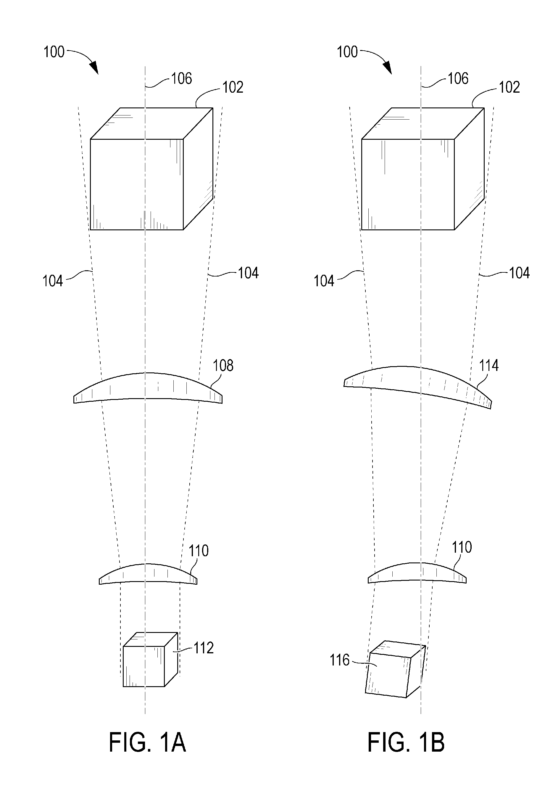
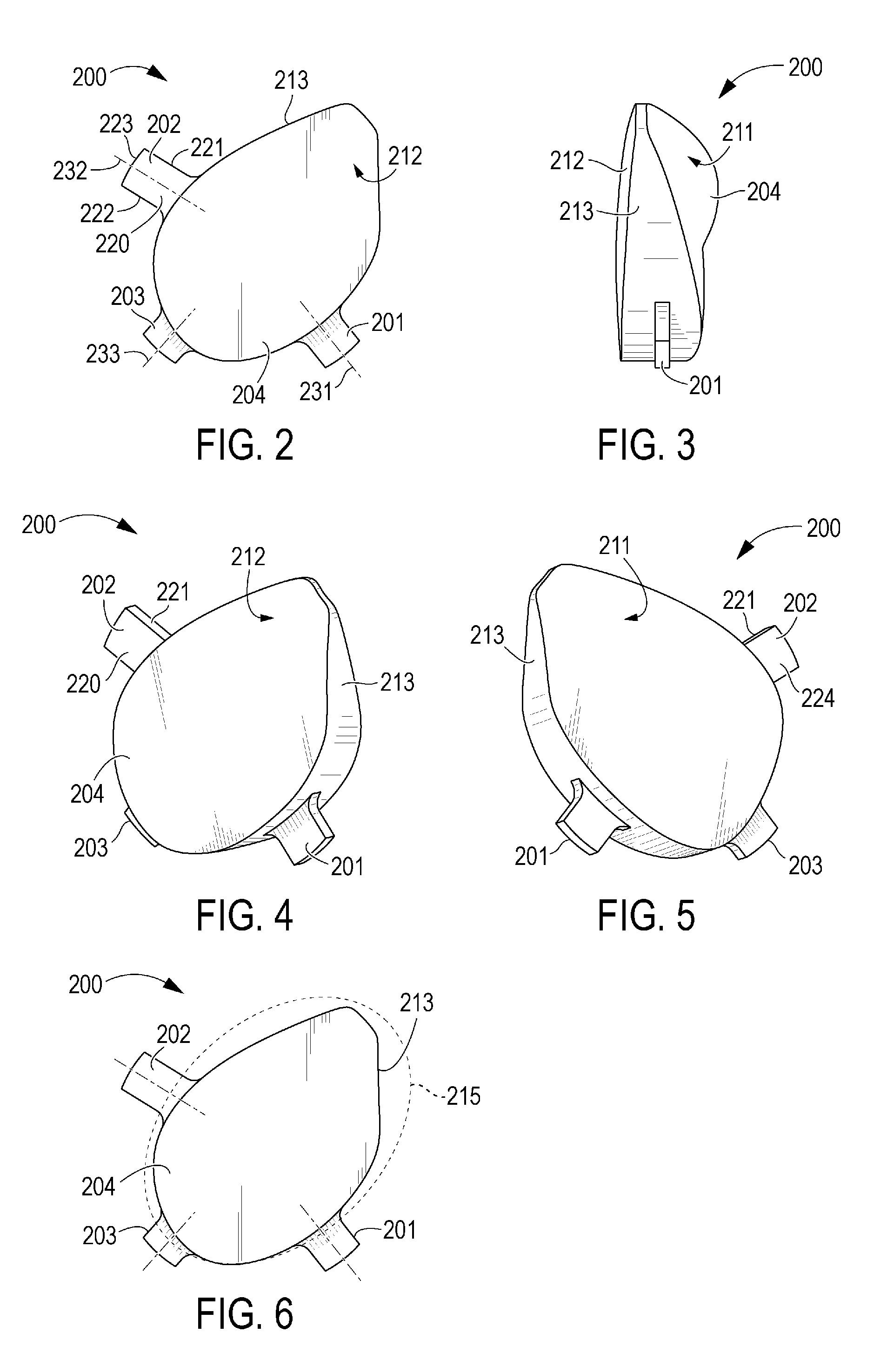
STATEMENT OF GOVERNMENT INTEREST[0001]The U.S. Government has a paid-up license in this invention and the right in limited circumstances to require the patent owner to license others on reasonable terms as provided for by the terms of Contract Number N00421-04-D-0010 awarded by the Naval Air Warfare Center AD (PAX).BACKGROUND OF THE INVENTION[0002]The present principles generally relate to optical systems, and more particularly, to a system and method for alignment of optical elements in relation to each other in an optical device using references on the optical elements.[0003]Within the art of optical device design, multiple optical lenses are commonly used together in a variety of optical devices. Multiple lenses (often referred to as a “lens train”) are commonly used in optical devices such as cameras, telephoto lenses, binoculars, telescopes, microscopes, night vision scopes, vehicular and marine periscopes, and the like.[0004]When fabricating optical devices with multiple lense...

Claims


Application Information

Patent Timeline
IPC IPC(8): G02B7/02B23P11/00
CPCG01M11/04G02B7/022Y10T29/49826G02B7/025G02B7/023
Inventor ASHCRAFT, TODD W.ATAC, ROBERT B.RISBOSKIN, JAMESALLARD, TIMOTHY G.FONTANELLA, JOSEPH J.TREMBACK, MARK J.
Owner THALES VISIONIX
Learn More