High-frequency module
- Summary
- Abstract
- Description
- Claims
- Application Information
AI Technical Summary
Benefits of technology
Problems solved by technology
Method used
Image

Examples
Embodiment Construction
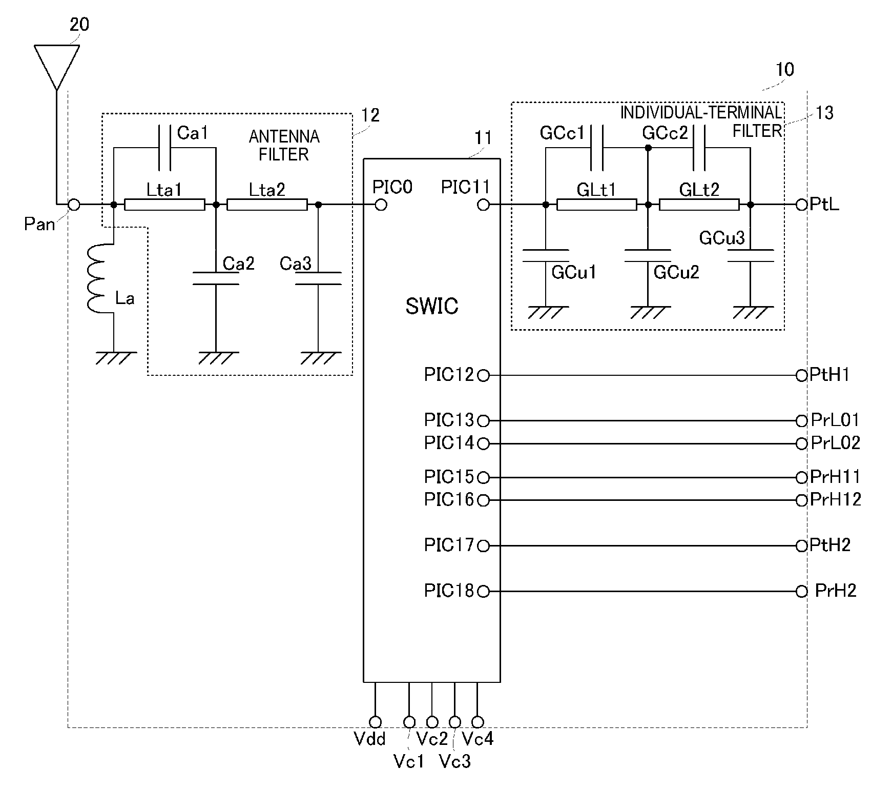
[0028]A high-frequency module according to a first preferred embodiment of the present invention is described below with reference to the drawings. FIG. 1 is a circuit diagram illustrating the configuration of a high-frequency module 10 of the first preferred embodiment.
[0029]The high-frequency module 10 preferably includes a switch IC 11, an antenna filter 12, and an individual-terminal filter 13. The high-frequency module 10 preferably includes a multilayer body and circuit elements mounted on the top surface of the multilayer body. The switch IC 11 is preferably a surface mount IC, and is mounted on the top surface of the multilayer body. The antenna filter 12 and the individual-terminal filter 13 preferably include inductors and capacitors, for example. In this case, based on the configuration of the high-frequency module 10 and the required values of the circuit elements, many possible inductors and capacitors may preferably be defined by interlayer electrode patterns provided ...
PUM
 Abstract
Description
Claims
Application Information
 - R&D
- Intellectual Property
- Life Sciences
- Materials
- Tech Scout
- Unparalleled Data Quality
- Higher Quality Content
- 60% Fewer Hallucinations
Browse by: Latest US Patents, China's latest patents, Technical Efficacy Thesaurus, Application Domain, Technology Topic, Popular Technical Reports.
© 2025 PatSnap. All rights reserved.Legal|Privacy policy|Modern Slavery Act Transparency Statement|Sitemap|About US| Contact US: help@patsnap.com