
Method of tactical training using a portable structure and a portable structure

Inactive Publication Date: 2011-12-08
DIDIER STEVEN J +1
View PDF5 Cites 18 Cited by
  • Summary
  • Abstract
  • Description
  • Claims
  • Application Information

AI Technical Summary

Benefits of technology

[0005]Phoenix's Portable Reality-Based Training Facility gives immediate freedom to agency personnel with the ability to conduct training away from the constraints of permanent structures. These multipurpose facilities provide that freedom by being portable, collapsible, reconfigurable, maneuverable and cost effective. The facilities can be utilized indoors as well as outdoors and will facilitate all types of law enforcement, military and private sector security training to include basic, refresher, in-service and advanced. With this facility agencies now have the ability to conduct training at their will, schedule, and budget. Agencies can now have a reality-based functional facility at any location such as in conference rooms, mat rooms, open fields, parking lots, firearm ranges, etc. These portable facilities allow static, dynamic and interactive training in instruction to include but not limited to tactics, control tactics, defensive tactics, use of force, close quarter battle, NLTA, firearms, cover courses, search and arrest warrants, briefings, interviews, role playing, scenarios and lectures, the combination of which are non-exclusively included in the definition of “tactical training”.
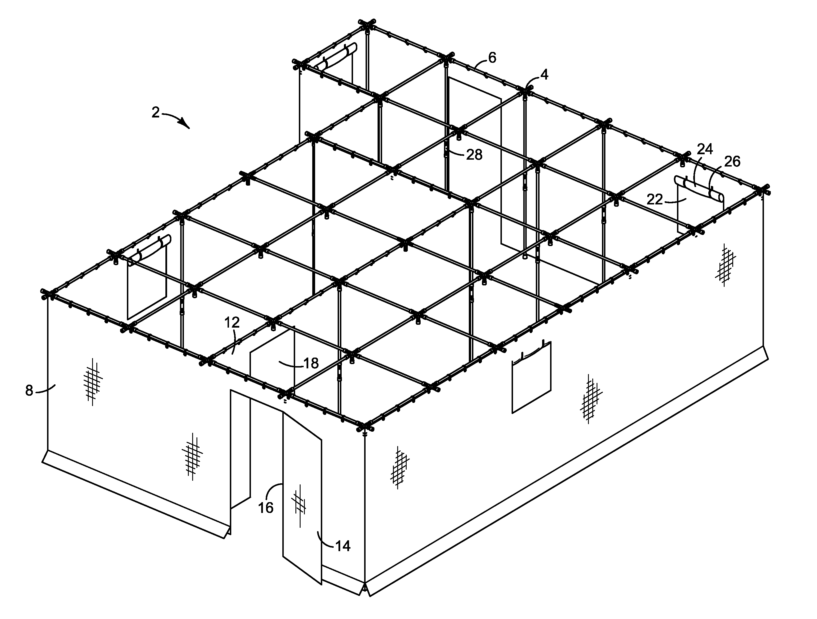
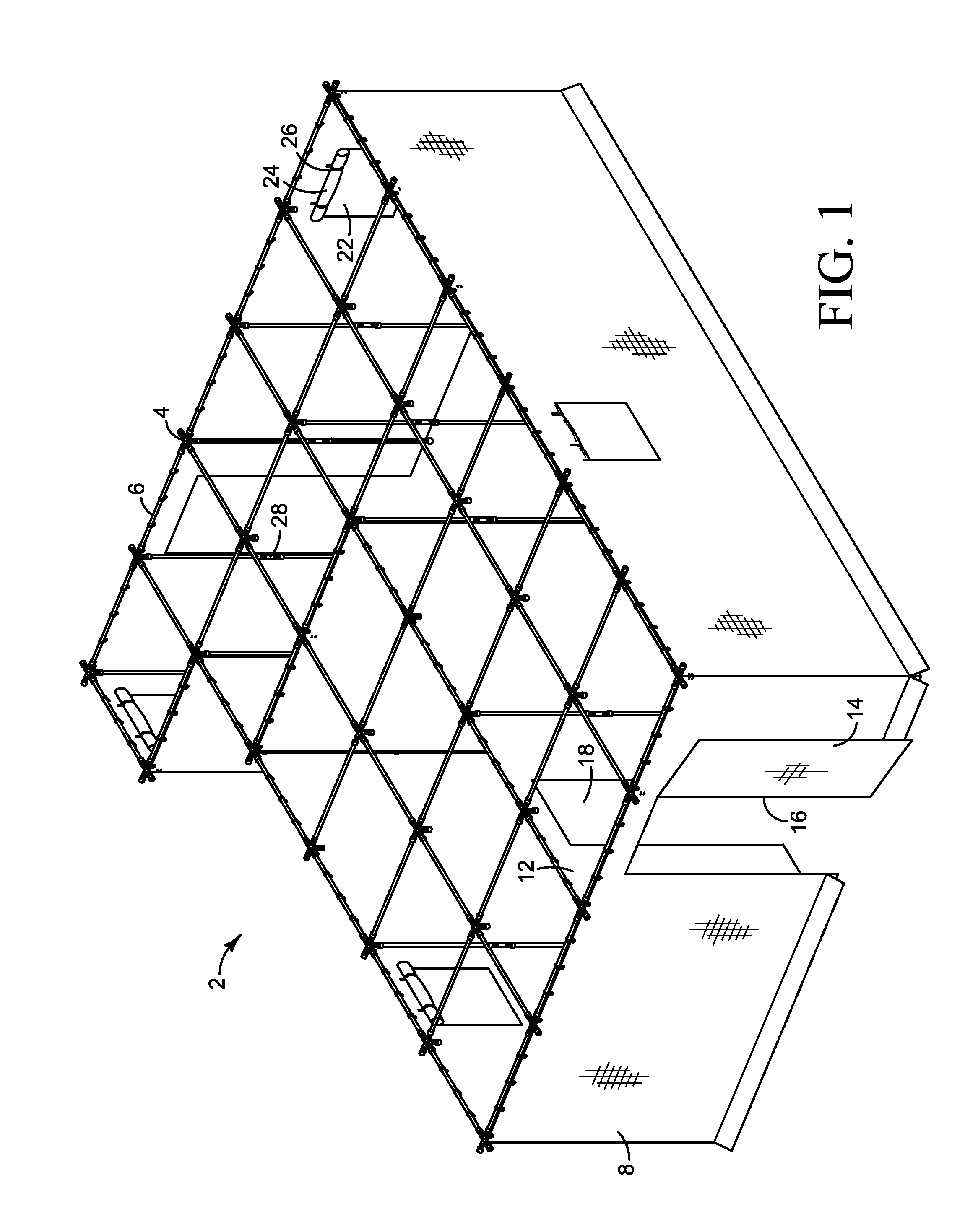
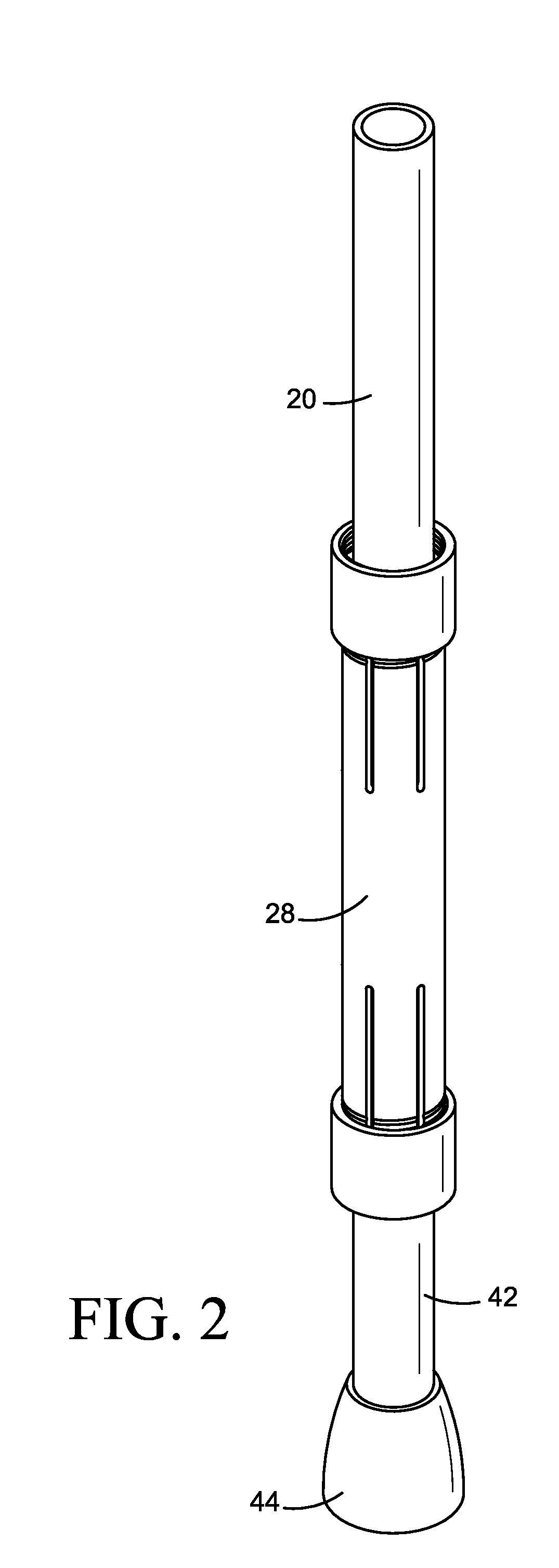
[0010]The room support structure, in a preferred embodiment, is assembled by attaching a plurality of wall supports to a series of wall support connectors. In a preferred embodiment, one type of wall support used generally has a first end, a second end, and a length between the first end and the second end. In a preferred embodiment these wall supports are tubular and are configured to connect to the wall connectors. The supports are generally made of PVC, plastic, aluminum, or similar structural material. The first and second ends of the wall support are configured to connect to wall support connectors. There are generally two types of wall support connectors that are used in the preferred embodiment of the invention, although a wide variety of wall support connectors can be used. In a preferred embodiment, a corner connector of the wall support generally has a first axis and a second axis in a horizontal plane. The first axis and second axis intersect at a generally perpendicular angle with the wall support connector having a first end and a second end on each of the first axis and second axis. This forms generally an X shape. In a preferred embodiment, from generally the intersection of the two axes in the X shaped connector extending in a vertical direction is a third axis. While the connector is X-shaped in a preferred embodiment, it is not mandatory that the connector be made in an x-shape. This third axis has a first end that is attached to the X shape generally at the intersection of the first axis and second axis and proceeds at a generally perpendicular direction from the first axis and second axis. The corner connector is preferably configured to be a corner connector, although it can also be used as a side connector or end connector provided a wall support is not connected to either the first or second axis. A plurality of the wall support connectors and wall supports forming a corner are connected to form a general room of the structure. These wall supports can be made to be extendable or they can be made such that a second connector connects two wall supports to form a larger structure. The second connector generally is a wall support connector having a first end and a second end and defining a length between the first end and second end. In a preferred embodiment the second connector is used to connect two wall supports. However, the second connector can be use to connect a variety of wall supports and / or wall connectors to for the portable structure frame. This allows for flexibility in the length of the wall supports. The connector can have threaded ends in order to have wall supports attach to the wall support connector or can have any other known method of attachment.

Problems solved by technology

The problem is there are an extra ordinate amount of law enforcement personnel, soldiers, and security that are not new hires.
Agencies then are left with few choices and a multitude of constraints consisting of availability and location, structure usability and functionality, leases and rental fees, undesirable locations and costly travel.
Although there are a few private constructed training facilities in the United States, those facilities are space and usability limited based on availability, location, access and cost again leaving agencies still with no viable options for facilities to conduct needed training.

Method used


Image

  • Method of tactical training using a portable structure and a portable structure
  • Method of tactical training using a portable structure and a portable structure
  • Method of tactical training using a portable structure and a portable structure

Examples


Embodiment Construction

[0025]While the presently disclosed inventive concepts are susceptible of various modifications and alternative constructions, certain illustrated embodiments thereof have been shown in the drawings and will be described below in detail. It should be understood, however, that there is no intention to limit the inventive concepts to the specific form disclosed, but, on the contrary, the presently disclosed and claimed inventive concepts is to cover all modifications, alternative constructions, and equivalents falling within the spirit and scope of the inventive concepts as defined in the claims.

[0026]In the following description and in the figures, like elements are identified with like reference numerals.

[0027]The use of “e.g.,”“etc,” and “or” indicates non-exclusive alternatives without limitation unless otherwise noted.

[0028]The use of “including” means “including, but not limited to,” unless otherwise noted.

[0029]FIG. 1 represents a preferred embodiment of the current invention. ...


PUM


Abstract

Disclosed is a portable training structure and a method for tactical training using a portable structure.

Description

PRIORITY / CROSS-REFERENCE TO RELATED APPLICATIONS[0001]This application claims the benefit of U.S. Provisional Application No. 61 / 350993, filed Jun. 3, 2010, the disclosure of which is incorporated by reference.TECHNICAL FIELD[0002]The disclosure generally relates to the field of portable structures and strategic training methods. Particular embodiments relate to portable structures and combat and / or tactical training methods incorporating portable structures.BACKGROUND[0003]Currently law enforcement, military and private sector security training is conducted at designated academies or bases nationwide. Historically, priority for training is given to basic training or new hires and as such these facilities are continually at capacity. The problem is there are an extra ordinate amount of law enforcement personnel, soldiers, and security that are not new hires. They are mandated by law, regulation or policy to attend refresher, in service and advanced training. If the existing faciliti...

Claims


Application Information

Patent Timeline
IPC IPC(8): G09B9/00
CPCE04H1/12E04B1/34326E04H1/125
Inventor DIDIER, STEVEN J.LAMBRAIA, ANTHONY
Owner DIDIER STEVEN J
Learn More