
Jumper

a technology of subterranean oil and apparatus, which is applied in the direction of connection contact material, connection device connection, borehole/well accessories, etc., can solve the problems of leakage between the sections of the conduit section and the surrounding underground formation, and achieve enhanced electrical conductivity, reduced oil leakage, and enhanced electrical conductivity

Active Publication Date: 2011-12-08
ELECTRO PETROLEUM
View PDF54 Cites 3 Cited by
  • Summary
  • Abstract
  • Description
  • Claims
  • Application Information

AI Technical Summary

Benefits of technology

[0003]The present invention provides a electrical jumper for bridging the joints between the adjoining conduit sections to insure electrical conductivity between the conduit sections, reducing the loss of voltage which may occur when the joints deteriorate.
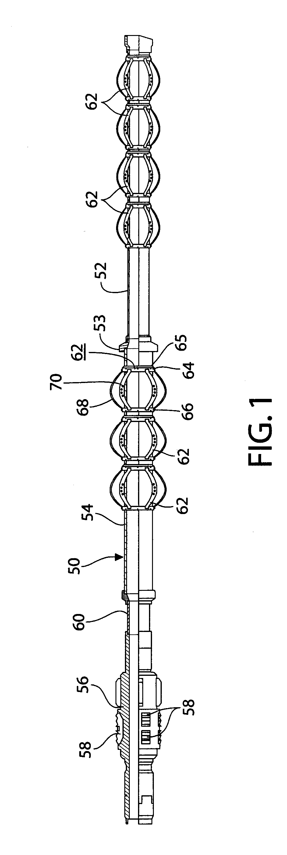
[0008]The invention may also insure enhanced electrical conductivity by providing electrical contacts on the bowed springs where they bear against the internal bore of the associated conduit section to enhance the electrical conductivity between the bowed spring and the ring which is electrically connected to the tubing, for example by welding.
[0009]The jumper may be modified to reduce oil leakage through the joint between the interiors of the conduit sections and the surrounding underground formation.

Problems solved by technology

It has been found that the joints between the conduit sections sometimes separate or deteriorate to a point where there is a substantial loss of voltage between adjacent conduit sections, and a possibility of leakage between the sections of the conduit sections and the surrounding underground formation.

Method used


Image

  • Jumper
  • Jumper
  • Jumper

Examples


Embodiment Construction

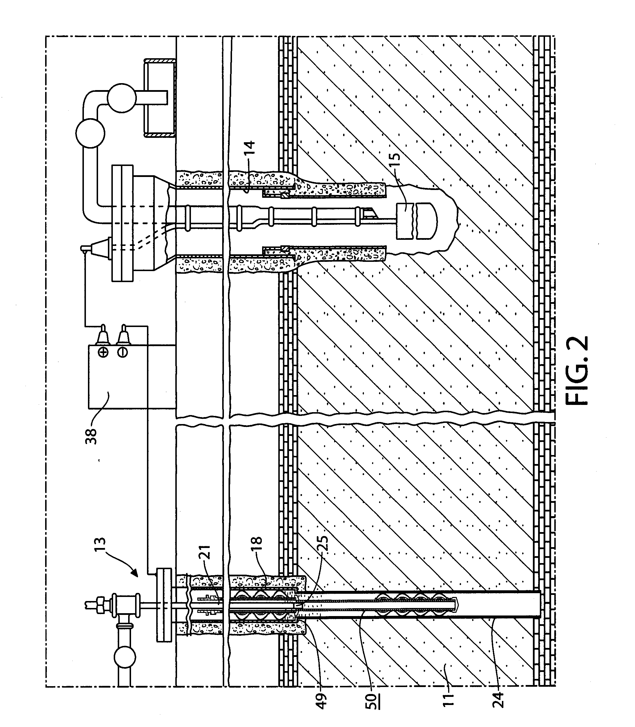
[0016]Referring to FIG. 2, the drawing illustrates an oil producing well 13 of the type shown in U.S. Pat. No. 7,325,604. The well 13 has a bore hole penetrating the oil-bearing formation 11 having a foraminous liner 24 which is connected to a casing 18 extending from the surface to the top of the formation 11 by a connecting joint at 49. The liner and casing are metallic and are connected to the negative terminal of an electric voltage source 38. A second bore hole 14 penetrates the oil formation 11 and encloses an electrode 15 which is connected to the positive terminal of the voltage source 38. As set forth in the above patent, the voltage source supplies an electric signal which has been found to enhance the production of oil from the formation 11. A pump 25 is mounted in the casing and has piping 21 for discharging the oil accumulating at the bottom of the casing 18. The casing and the liner constitute conduit sections which are effective to conduct oil from the oil-bearing for...


PUM


Abstract

A jumper for insuring electrical or fluid communication between the liner and the casing of an oil field downhole. The jumper has a first tubing adapted to be inserted in the liner, a second tubing adapted to be inserted in the casing and an anchor adapted to be rigidly mounted in the casing. The first and second tubings are composed of an electrically conductive material and are supported by the anchor with an insulated joint. Each of the first and second tubings has a plurality of centering devices, each consisting of a pair of rings surrounding the tubing and an array of bowed springs bridging between the rings and biased to bow outwardly from the tubing into engagement with the inner circumference liner or the casing, as the case may be. One of the two rings is electrically connected to the tubing, for example by welding, whereas the other ring is free to be displaced longitudinally of the tubing so that the outer diameter of the array of bowed springs may expand or contract, as needed. Each bowed spring in the array is provided with a series of electrical contacts which insure electrical conductivity between the welded ring and the surrounding liner or casing through the bowed spring.

Description

FIELD OF INVENTION[0001]The present invention relates to apparatus for enhancing the production of oil from subterranean oil reservoirs with the aid of electric current and, in particular, apparatus for enhancing the performance of the method described in U.S. Pat. No. 7,325,604, issued Feb. 5, 2008, the entire contents of which are incorporated herein by reference.BACKGROUND OF THE INVENTION[0002]As set forth in more detail in U.S. Pat. No. 7,325,604, the oil bearing formation is tapped by drilling a downhole into the oil-bearing formation and providing a downhole liner to form an open conduit for the removal of oil. The liner is foraminous in order to permit the oil to enter the conduit throughout the length of the liner. It has been found that the production of oil is enhanced by connecting a negative electrode to the liner and introducing a second electrode in proximity to the formation. A voltage difference is established between the first and second electrodes to create an ele...

Claims


Application Information

Patent Timeline
IPC IPC(8): H01R31/06
CPCE21B17/003H01R13/17H01R4/64E21B43/16
Inventor WITTLE, J. KENNETHHARRISON, JAMES
Owner ELECTRO PETROLEUM
Learn More