
Solid elastic lens element and method of making same

a technology of elastic lens element and solid layer, applied in the field of solid layer lens element, can solve the problems of unreliable and unpredictable system of lens element use, unreliable solid layer and motorized system,

Active Publication Date: 2011-12-01
HAND HELD PRODS
View PDF13 Cites 14 Cited by
  • Summary
  • Abstract
  • Description
  • Claims
  • Application Information

AI Technical Summary

Benefits of technology

[0020]In another aspect of the invention, a method is provided for manufacturing a lens element. The method includes the steps of providing a housing and a light transmissive cover, forming a first elastic solid lens from polydimethylsiloxane cross linked with an agent in a ratio of greater than 20:1, secu...

Problems solved by technology

Fluid lens element technology has attracted the attention of many designers of optical systems who generally see traditional solid lens elements and motor equipped systems as bulky and energy hungry.
Problems have been noted with all three methods for varying an optical property of a fluid lens element.
Regarding electro wetting, one problem that has been noted is that the electrical current repeatedly flowing through the lens element tends to alter the characteristics of the lens element over time, rendering any system in which the lens element is employed unreliable and unpredictable.
Another problem noted with proposals involving electro wetting is that electro wetting normally involves providing two types of fluids.
Regarding the fluid injection methods, the pumps for providing such fluid injection are necessarily complex and intricate making a reasonably costly system and acceptable miniaturization difficult to achieve.
Regarding the mechanical actuation methods, manufacture of the lens element assembly has proven problematic due to the difficulty in handling the focus fluid.
Furthermore, the assembly cannot sustain high temperature operation (e.g., above 45 degrees Celsius) due to the weak structure of the deformable membrane with focus fluid inside the cavity.
Further, the assembly is susceptible moisture and environmental effects, thereby limiting the lifespan.
Finally, and most critically, the fluid lens is susceptible to leakage over the lifetime of usage.
Yet, the miniaturization and energy conservation achievable with motor-actuated rigid element equipped optical systems continues to be limited.

Method used


Image

  • Solid elastic lens element and method of making same
  • Solid elastic lens element and method of making same
  • Solid elastic lens element and method of making same

Examples


Embodiment Construction

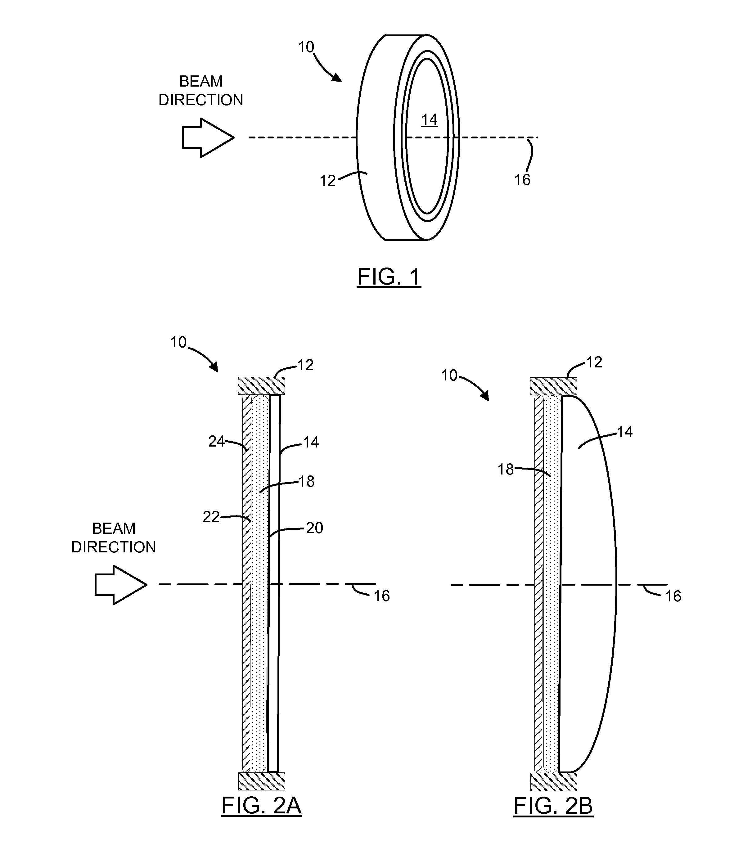
[0039]Referring to FIGS. 1 and 2A, there is shown a perspective and cross sectional side views respectively of a lens element 10. The lens element 10 includes a housing 12, two light transmissive elastic solid lenses, and a light transmissive cover 14. In the illustrated embodiment, the housing 12 is a simple ring-like construction into which the cover 14 is press-fit. The two lenses are nested against the cover 14. Other constructions for the housing 12 are possible, as will be explained in detail below. Together, the two elastic solid lenses and the cover 14 define an optical axis 16.

[0040]The light transmissive cover 14 may be provided by a solid light transmissive material with or without optical power, or by a deformable membrane capable of exhibiting curvature for definition of a lens surface having optical power, such as that illustrated in FIG. 2B. In the illustrated embodiment, the light transmissive cover 14 is a solid piece of glass.

[0041]A first elastic solid lens 18 is ...


PUM

PropertyMeasurementUnit
Thicknessaaaaaaaaaa
Thicknessaaaaaaaaaa
Thicknessaaaaaaaaaa

Abstract

A lens element is provided that includes a housing defining a center bore and an optical axis, and a light transmissive cover coupled to the housing. A first elastic solid lens is disposed within the housing adjacent the light transmissive cover, and is characterized by a first thickness and a first durometer hardness. A second elastic solid lens is disposed in the housing adjacent to and substantially conforming to the first elastic solid lens, and is characterized by a second thickness and a second durometer hardness. The second lens thickness is less than the first lens thickness, and the second durometer hardness is greater than the first durometer hardness. In one embodiment, the first durometer hardness is less than OO60 as measured by the Shore method, and the second durometer hardness is in the range of A20 to A60 as measured by the Shore method.

Description

FIELD OF THE INVENTION[0001]This disclosure relates generally to a lens element for incorporation into an optical imaging system and, more specifically, to a lens element comprising a plurality of solid elastic lenses.BACKGROUND OF THE INVENTION[0002]Variable lenses, e.g., multiple focus lenses and zoom lenses have traditionally employed one or more non-deformable (i.e., rigid such as glass or polycarbonate) lens elements which are moved along an imaging axis by forces often supplied by a motor.[0003]In recent years, motorless electro-responsive lens elements have attracted increased attention of researchers and designers of optical systems. One type of motorless electro-responsive lens element is the “fluid lens” lens element which generally includes a rigid or elastomeric membrane filled with one or more fluids having indices of refraction greater than 1. Fluid lens element technology has attracted the attention of many designers of optical systems who generally see traditional so...

Claims


Application Information

Patent Timeline
IPC IPC(8): G06K7/10G02B1/00B23P11/00G02B11/00
CPCG02B3/14G02B7/04Y10T29/49826G02B26/0875G02B13/0075G02B7/28
Inventor WANG, YNJIUN PAULFENG, CHEN
Owner HAND HELD PRODS
Learn More