
Medical device for tissue ablation

a medical device and tissue technology, applied in the field of medical devices for tissue ablation, can solve the problems of heart failure and stroke, undesirable or intolerable side effects, and excessive heart beat, and achieve the effect of reducing the ability of the atria

Inactive Publication Date: 2011-11-24
MAESTROHEART
View PDF8 Cites 94 Cited by
  • Summary
  • Abstract
  • Description
  • Claims
  • Application Information

AI Technical Summary

Benefits of technology

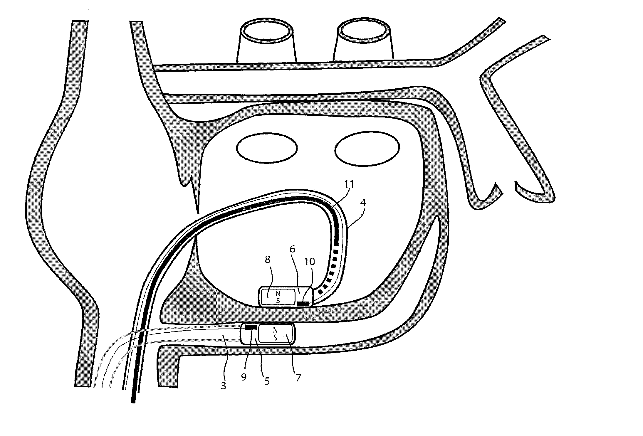
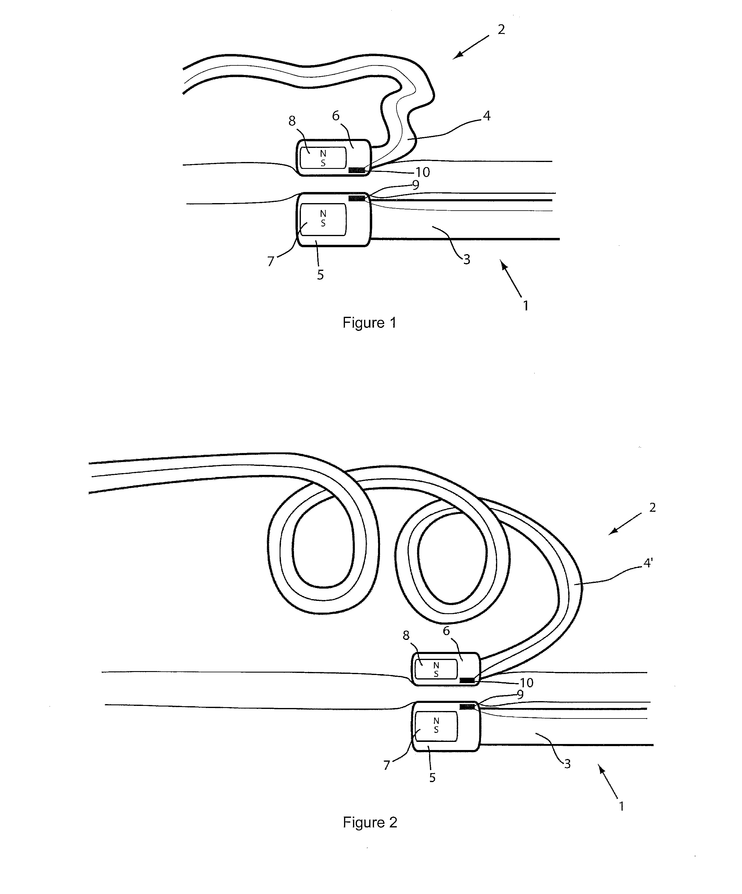
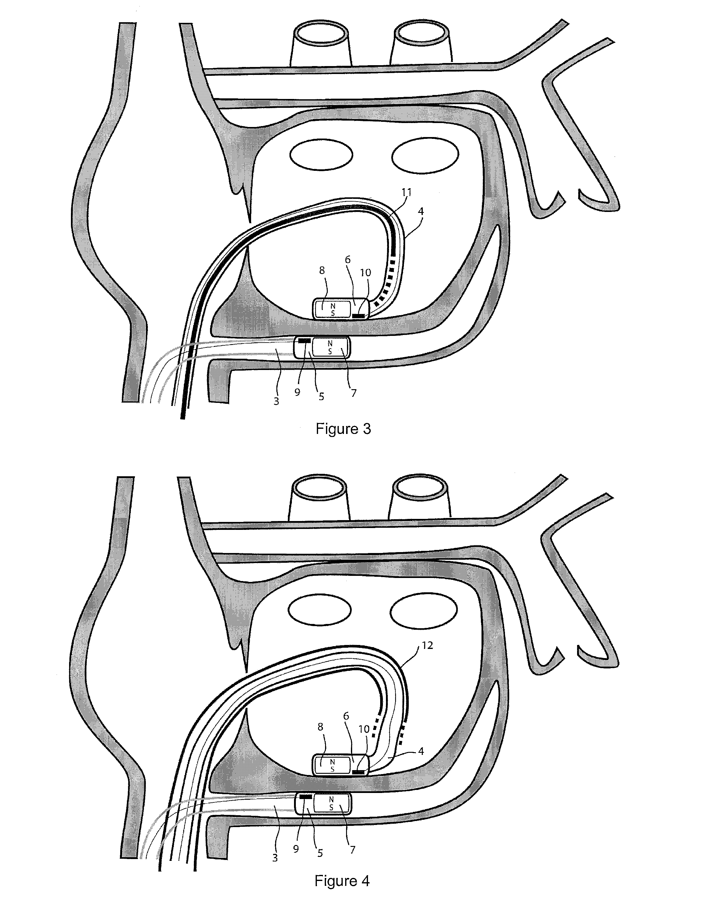
"The present invention aims to improve tissue ablation devices, specifically the ablation device described in WO 2008 / 010039. The invention provides a system that allows for precise control of the ablation electrode positioning and movements during intervention, while also monitoring relevant physiological parameters to prevent complications. The invention also makes it easy to guide the use of the device and improves its positioning during use."

Problems solved by technology

Atrial fibrillation reduces the ability of the atria to pump blood into the lower chambers of the heart (the ventricles) and usually causes the heart to beat too rapidly and may induce complications that include heart failure and stroke.
While medication has been used to prevent recurrence of atrial fibrillations, they are not always effective and may induce undesirable or intolerable side effects.
Furthermore they do not cure the underlying causes.
Implantable devices have also been used but they only correct the arrhythmia after it occurs and do not help to prevent it.
However, this technique presents several difficulties.
The currently used techniques of manual catheter ablation as well as robotic ablation systems in development do not allow precise controlled movements of the ablation electrode tip along the internal atrial wall surface.
The absence of real time visualisation of the atrial wall during the intervention hampers the generation of precise continuous ablation lines.
The gaps between ablation points are commonly leading to a lack of treatment efficacy and may induce development of atrial flutter.
Another known problem relates to the determination of the correct level of energy to deliver to the ablation tip so as to precisely control the ablation lesion depth.
When the catheter distal end is not correctly positioned or when the ablation electrode is not perpendicular to the cardiac tissue, energy applied may be either too low, in that case the lesion is ineffective, or too high which may lead in rare cases to atrial wall perforation, oesophageal burns and atrial-oesophageal fistula formation.
This complication, although rare, is extremely devastating and fatal in more than half of the reported cases.
The use of a temperature sensor at the tip of the catheter in the vicinity of the ablating electrode does not help to solve this problem as it does not provide an accurate measure of the tissue temperature because the measure is mostly influenced by the heating of the ablation electrode and its cooling by the irrigation liquid when RF energy is applied.

Method used


Image

  • Medical device for tissue ablation
  • Medical device for tissue ablation
  • Medical device for tissue ablation

Examples


Embodiment Construction

[0038]For the basic description of the device according to the invention, reference is made to WO 2008 / 010039 mentioned above in the present specification and incorporated in its entirety in the present application.

[0039]A first problem one has been confronted with when using the system described in WO 2008 / 010039 mentioned above is the “guidability” of the guided member. As indicated and described in this incorporated prior art, the idea then was to provide a system with two elongated members, used in particular for ablation, having at their distal end at least a magnet or a magnet arrangement for a magnetic coupling of said distal end when they are brought close together. Experiments with prototypes of the system described in the WO 2008 / 010039, show that the guiding member should be more rigid than the guided member to allow a proper functioning of the system. In fact, it was observed that the less rigid or the more flexible the guided member is, the better it follows the guiding...


PUM


Abstract

A medical device for ablating tissues within a heart chamber comprising a first guiding member intended to be introduced in the hollow structure surrounding the left atrium of the patient and a second ablating member comprising an ablation electrode mounted at the distal end or tip of catheter. Both, the head of the guiding member and the tip of the ablating member are magnetised and can enter into magnetic coupling when their distal ends are brought in close contact. Once the magnetic coupling is achieved, the tip of the first member is guided by moving the guiding member. Preferably, the guiding member includes sensors enabling to monitor physiological parameters during the intervention.

Description

TECHNICAL FIELD[0001]The present invention relates to an improved medical device or apparatus for ablating cardiac tissues along continuous lines in the heart chambers. A further object of the invention relates to a method for positioning and guiding an ablation catheter during ablation procedure. More particularly the device and method of the present invention are intended to perform ablation lines on the wall of the left atrium in order to treat and prevent the occurrences of atrial fibrillation. The medical device comprises to that extent a first elongated member having a distal end comprising an ablation electrode and a second elongated member allowing precise control of the ablation electrode.BACKGROUND ART[0002]Abnormal heart rhythms are generally referred to as cardiac arrhythmias and with an abnormally rapid rhythm called tachycardia. Atrial fibrillation is an abnormal rhythm of the heart caused by abnormal electrical discharges within the two upper chambers of the heart cal...

Claims


Application Information

Patent Timeline
Patent Type & Authority Applications(United States)
IPC IPC(8): A61B18/14
CPCA61B18/02A61B18/1492A61B18/18A61B18/20A61B2017/00477A61B2018/00011A61M25/0127A61B2018/00351A61B2018/00791A61B2018/00875A61B2019/464A61B2218/002A61B2018/00029A61B2090/064
Inventor VERIN, VITALIFLACTION, LIONEL
Owner MAESTROHEART
Learn More