Ribbon transducer with improved distortion characteristics

a technology of distortion characteristics and ribbons, applied in the field of electroacoustic transducers, can solve the problems of undesirable vibration of return path wires within this magnetic field, undesirable undesirable acoustic distortion, etc., and achieve the effect of reducing electromagnetic modulation of static magnetic field and eliminating mechanical vibration of each return path wir

Inactive Publication Date: 2011-11-24
GEORGE E SHORT III
View PDF7 Cites 3 Cited by
  • Summary
  • Abstract
  • Description
  • Claims
  • Application Information

AI Technical Summary

Benefits of technology

[0009]In this invention, each return path wire is adhered to the frame assembly along most of its length with a layer of adhesive film such as adhesive tape, such that it is rigidly, attached to the frame assembly along most of its length and does not touch another return path wire along most of its length, the purpose of which is to eliminate mechanical vibration of each return path wire. This can be accomplished by adhering the return path wires widely spaced along the frame assembly, or by adhering the return path wires and adhesive film to the frame assembly in layers such that a layer of adhesive film separates each return path wire from the other return path wires along most of their length, or a combination of both.
[0010]As another aspect of this invention, the adhesive film applied to the return path wires as described above may contain an electrically conductive material (such as aluminum foil tape) or may be layered with electrically conductive material such that each individual return path wire is surrounded with electrically conductive material along most of its length. The electrically conductive layer acts to electromagnetically shield the return path wires from each other and from the diaphragm conductors. This reduces the ribbon transducer's electrical circuit self inductance and reduces electromagnetic modulation of the static magnetic field.

Problems solved by technology

Vibration of the return path wires within this magnetic field is undesirable because vibration induces an electromotive force on the electrons within the wires (called “back emf”) which then flow through the ribbon electrical circuit in the form of “back emf current”.
The back emf current distorts the electrical signal from the amplifier, leading to acoustic distortion.
In addition, the vibrating return path wires may create sound of their own or can buzz against each other and / or against the frame assembly.
Modulation of the static magnetic field is undesirable because it distorts the static magnetic field which in turn leads to acoustic distortion of the sound created by the diaphragm in motion.
Electrical self inductance is undesirable because it causes the transducer's electrical impedance to increase at high frequencies, creating electrical phase shift on the input electrical current and attenuating the acoustic output of the ribbon transducer at high frequencies.

Method used


Image

  • Ribbon transducer with improved distortion characteristics
  • Ribbon transducer with improved distortion characteristics
  • Ribbon transducer with improved distortion characteristics

Examples


Embodiment Construction

[0012]The invention was conceived of, designed and constructed as an electroacoustic transducer which displays improvement in dispersion and distortion.

[0013]This type of electroacoustic transducer is usually referred to as a “ribbon” transducer and is generally used for audio reproduction applications as a high frequency, mid-frequency or full range unit.

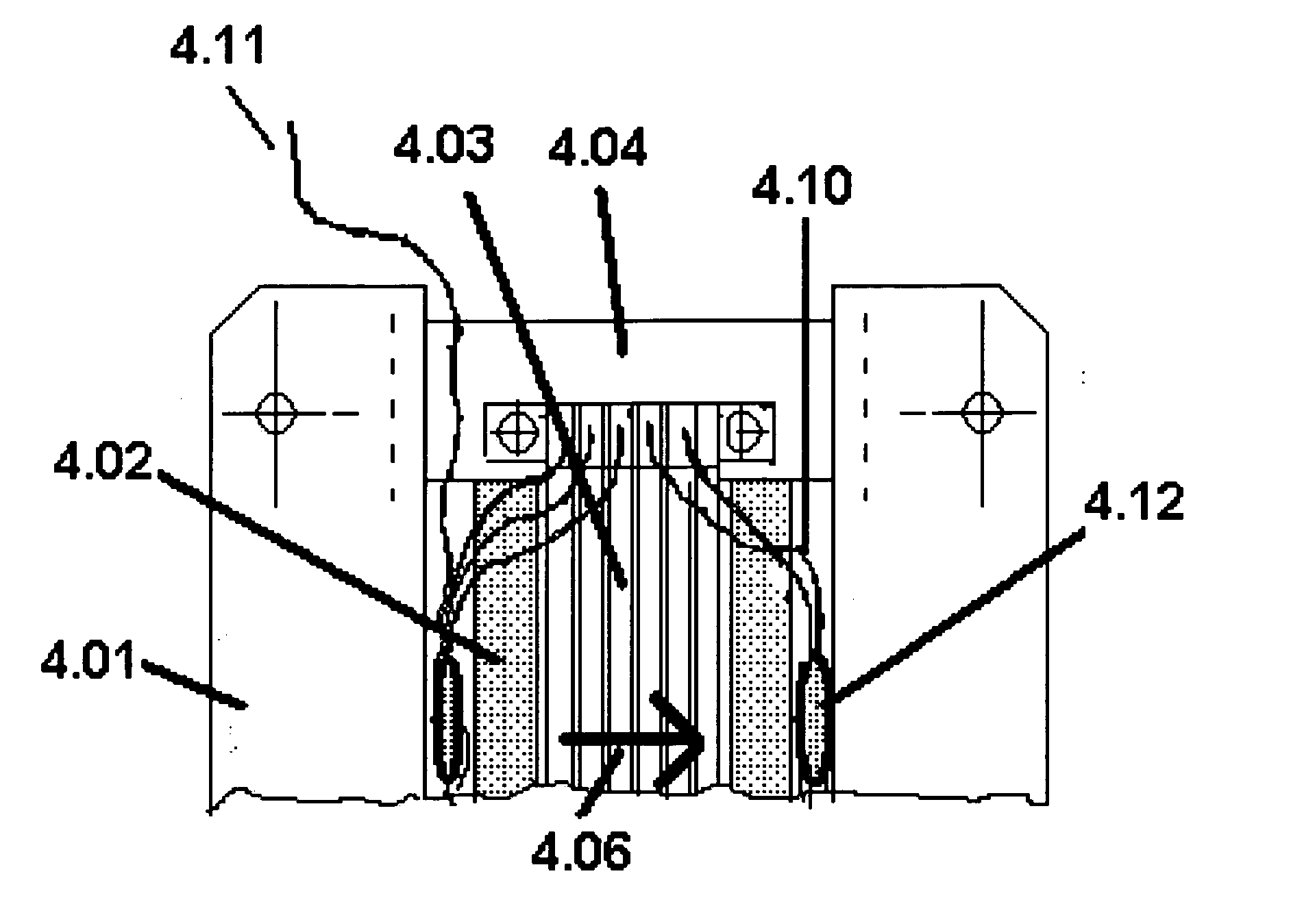
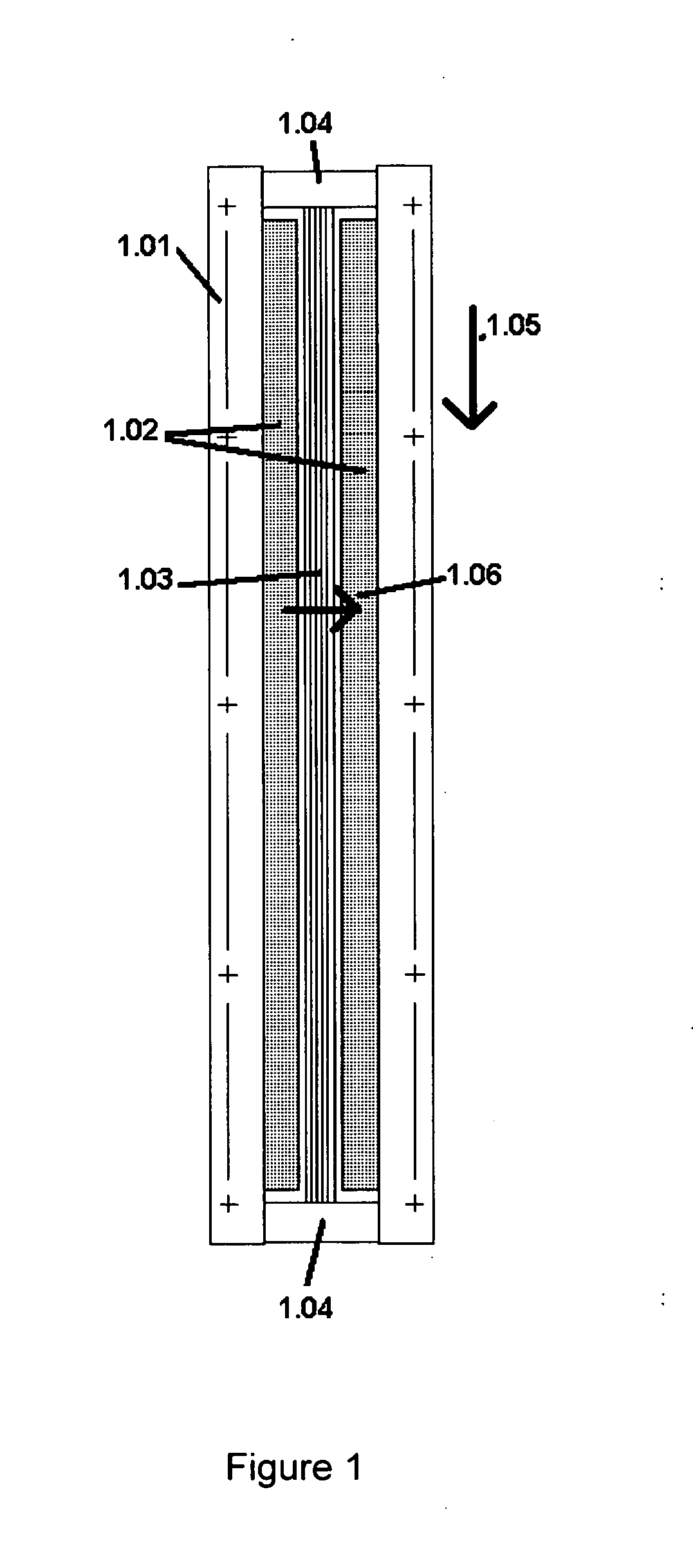
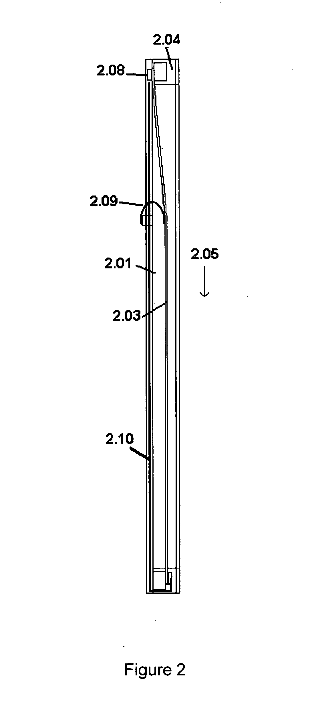
[0014]Many conventional ribbon transducer designs (FIGS. 1, 2, 3, 4, and 5) employ a diaphragm assembly (1.03, 2.03, 4.03, 5.03) made of several rows of conductive material (referred to as the “ribbon conductors”) (3.12) adhered to an electrically non-conductive film (3.11), forming a diaphragm assembly generally referred to as a “ribbon diaphragm assembly”. The diaphragm may or may not be corrugated, and may or may not be built into an arc. This ribbon diaphragm assembly is suspended between two parallel rows of magnets (1.02, 3.02, 4.02, 5.02) adhered to a steel frame (1.01, 2.01, 3.01, 4.01, 5.01). The frame is composed of two p...


PUM


Abstract

A ribbon-type electroacoustic transducer with improved electrical, electromechanical, electromagnetic characteristics is described.

Description

BACKGROUND OF THE INVENTION[0001]The invention was conceived of, designed and constructed as an electroacoustic transducer which displays improvement in distortion characteristics.[0002]This type of electroacoustic transducer is usually referred to as a “ribbon” transducer and is generally used for audio reproduction applications as a high frequency, mid-frequency or full range unit.[0003]Many conventional ribbon transducer designs employ a diaphragm assembly made of several rows of electrically conductive material (referred to as the “ribbon conductors”) adhered to an electrically non-conductive film, forming a diaphragm assembly generally referred to as a “ribbon diaphragm assembly”. The diaphragm may or may not be corrugated. This ribbon diaphragm assembly is suspended between two parallel rows of magnets adhered to a steel frame. The frame is generally composed of two parallel steel section connected to each other near their ends with cross members, and may have additional eleme...

Claims


Application Information

Patent Timeline
Patent Type & Authority Applications(United States)
IPC IPC(8): H04R11/04
CPCH04R1/06H04R2209/022H04R9/048
Inventor SHORT, III, GEORGE ELLIOTT
Owner GEORGE E SHORT III
Why Eureka
Try Eureka