
Stereoscopic Image Display Apparatus Capable Of Wirelessly Transmitting and Receiving Power

a display apparatus and wireless technology, applied in the field of stereoscopic image display apparatus capable of wireless transmission and receiving power, can solve the problems of poor glasses wearing sensation, high price, and poor picture quality in bright places when compared to active methods, and achieve the effect of reducing glasses weight and improving glasses wearing sensation

Inactive Publication Date: 2011-11-24
SAMSUNG ELECTRO MECHANICS CO LTD
View PDF4 Cites 13 Cited by
  • Summary
  • Abstract
  • Description
  • Claims
  • Application Information

AI Technical Summary

Benefits of technology

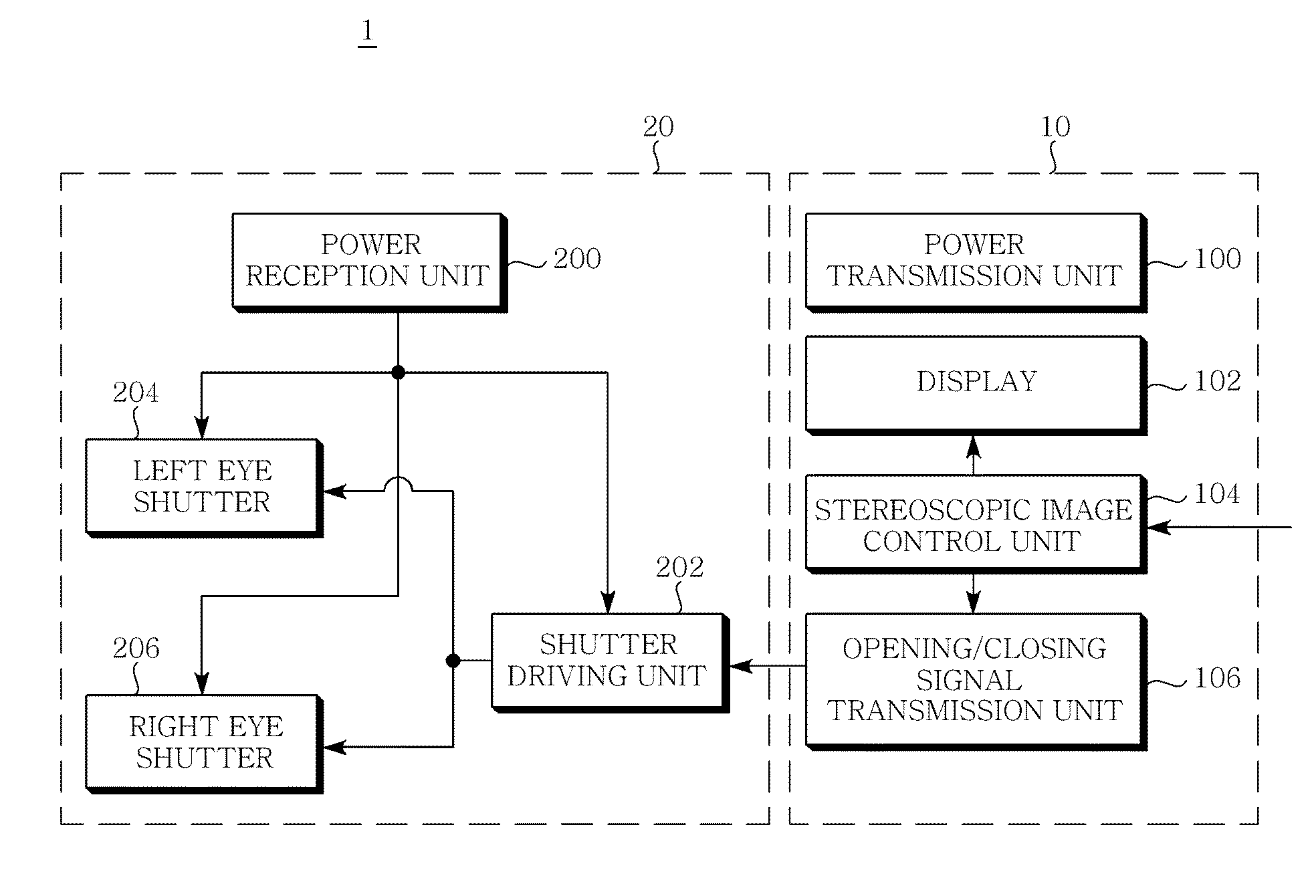
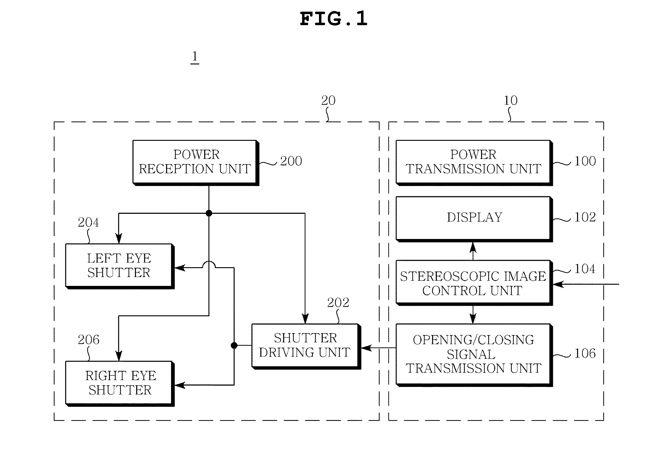
[0011]Accordingly, the present invention has been made keeping in mind the above problems occurring in the prior art, and the present invention is intended to provide 3D glasses capable of wirelessly receiving power and a stereoscopic system including the same, which wirelessly provide power, so that the weight of the glasses is reduced, thereby improving the sensation of wearing the glasses.

Problems solved by technology

In general passive methods, an expensive 3D filter is installed on a TV screen or a theater's screen, thereby realizing a 3D screen.
The passive method has advantages in that 3D images can be seen using glasses which do not include a special electric device and the price thereof is cheap, but has a disadvantage in that it doesn't have good picture quality in bright places when compared to the active method.
However, such an active method has disadvantages in that the price thereof is high because it requires an electric product which including an electric circuit and a battery used to open and close right and left shutters, and in that the sensation of wearing the glasses is not good because a battery is built in the glasses and the glasses are heavier than general glasses.

Method used


Image

  • Stereoscopic Image Display Apparatus Capable Of Wirelessly Transmitting and Receiving Power
  • Stereoscopic Image Display Apparatus Capable Of Wirelessly Transmitting and Receiving Power
  • Stereoscopic Image Display Apparatus Capable Of Wirelessly Transmitting and Receiving Power

Examples


Embodiment Construction

[0030]Herein, words and terms used in the present specification and claims must not be interpreted as having common and dictionary meanings, but should be interpreted as having meanings and concepts in conformity with the technical spirit of the present invention based on the principle in which an inventor can appropriately define the concepts of terms in order to describe the inventor's own invention in the most appropriate way.

[0031]Reference now should be made to the drawings, in which the same reference numerals are used throughout the different drawings to designate the same or similar components.

[0032]Further, when it is determined that the detailed descriptions of well-known techniques related to the present invention would obscure the gist of the present invention, they will be omitted below.

[0033]Embodiments of the present invention will be described in detail below with reference to the attached drawings.

[0034]FIG. 1 is a block diagram showing a stereoscopic image display ...


PUM


Abstract

Disclosed herein is a stereoscopic image display apparatus capable of wirelessly transmitting and receiving power. The stereoscopic image display apparatus includes a stereoscopic image display unit and shutter glasses. The stereoscopic image display unit divides stereoscopic images into images for the left eye and images for the right eye and displays the resulting stereoscopic images, generates a signal of opening / closing a right eye shutter and a left eye shutter, and generates a power signal and then wirelessly transmits power in a magnetic resonance coupling manner. The shutter glasses wirelessly receives the power signal from the stereoscopic image display unit in the magnetic resonance coupling manner, and provides the images for the left eye and the images for the right eye by alternatively opening and closing the left eye shutter and the right eye shutter in response to the signal of opening / closing the right eye shutter and the left eye shutter.

Description

CROSS REFERENCE TO RELATED APPLICATION[0001]This application claims the benefit of Korean Patent Application No. 10-2010-0047115, filed on May 19, 2010, entitled “Stereoscopic Display Apparatus for Receiving and Transmitting Power by Wireless,” which is hereby incorporated by reference in its entirety into this application.BACKGROUND OF THE INVENTION[0002]1. Technical Field[0003]The present invention relates to a stereoscopic image display apparatus capable of wirelessly transmitting and receiving power.[0004]2. Description of the Related Art[0005]Recently, the development of 3-Dimensional (3D) displays has been accelerated at the request of users who want to feel the sense of reality from a screen.[0006]Generally, methods of watching 3D Televisions (TVs) are divided into a method of watching a 3D TV with glasses and a method of watching a 3D TV without glasses. The method of watching a 3D TV with glasses has mainly been used in consideration of current technical levels and costs.[0...

Claims


Application Information

Patent Timeline
Patent Type & Authority Applications(United States)
IPC IPC(8): H04N13/04
CPCH04N5/63H04N13/0497H04N13/0438H04N13/341H04N13/398
Inventor KIM, EUNG JUHWANG, SHIN HWANKIM, JEONG HOON
Owner SAMSUNG ELECTRO MECHANICS CO LTD
Learn More