
Intra prediction modes

a prediction mode and intra-prediction technology, applied in signal generators with optical-mechanical scanning, color television with bandwidth reduction, etc., can solve the problems of reducing the efficiency of the overall video signal compression, real cost of increasing the number of total digital information that must be transmitted, etc., and achieve the effect of more accurate prediction

Active Publication Date: 2011-11-17
LG ELECTRONICS INC
View PDF7 Cites 237 Cited by
  • Summary
  • Abstract
  • Description
  • Claims
  • Application Information

AI Technical Summary

Benefits of technology

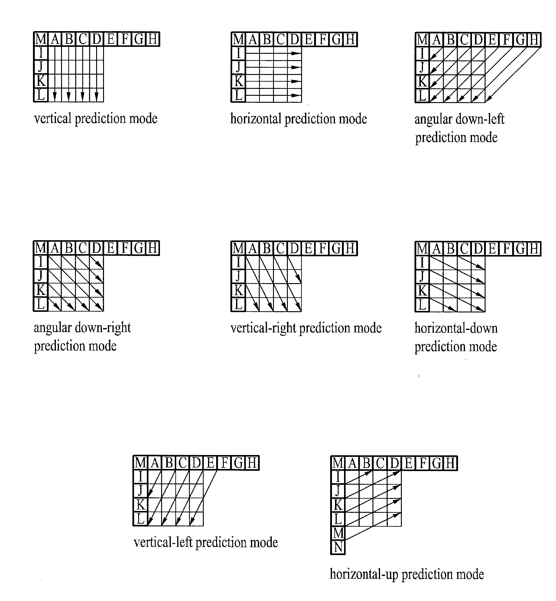
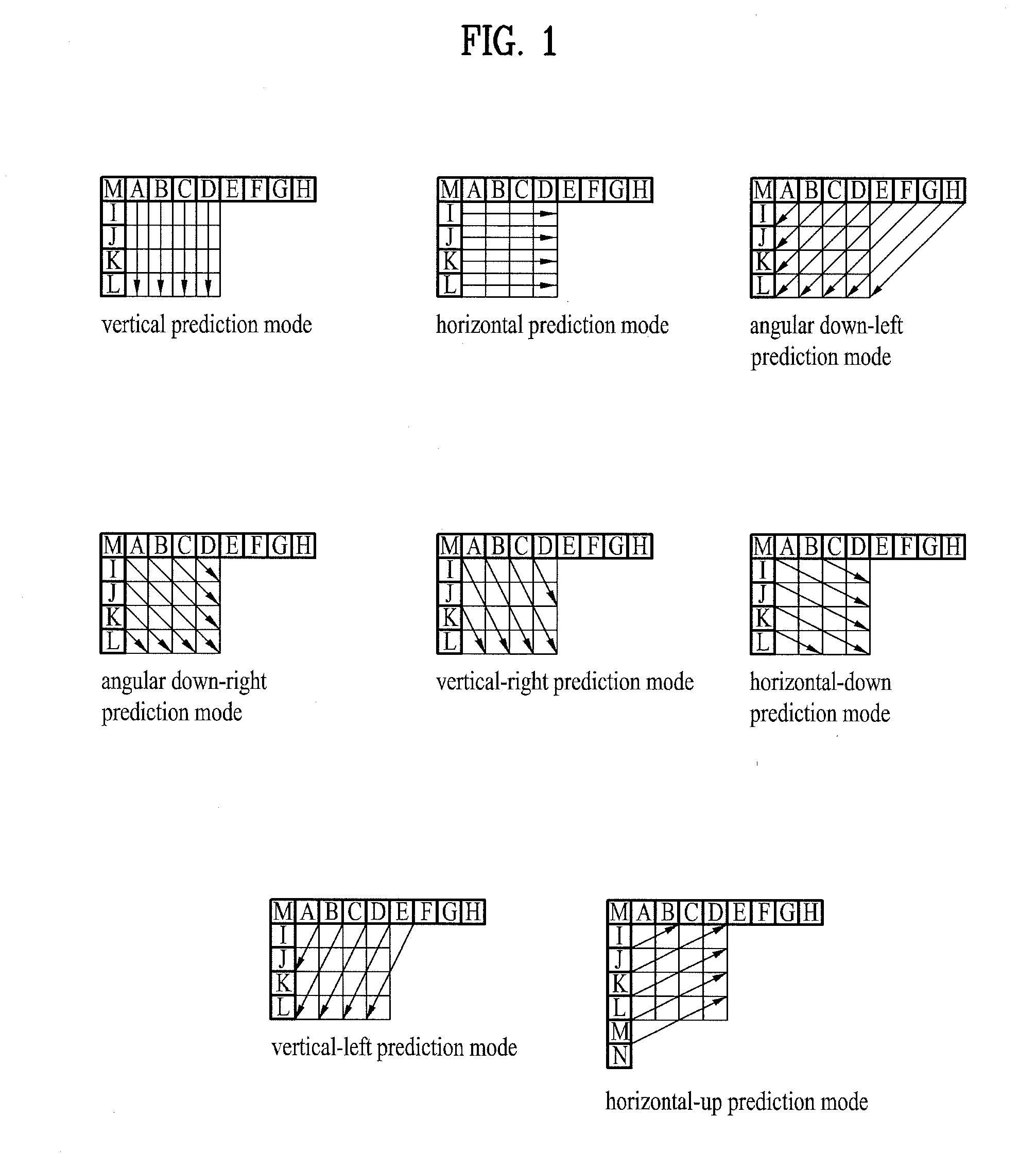
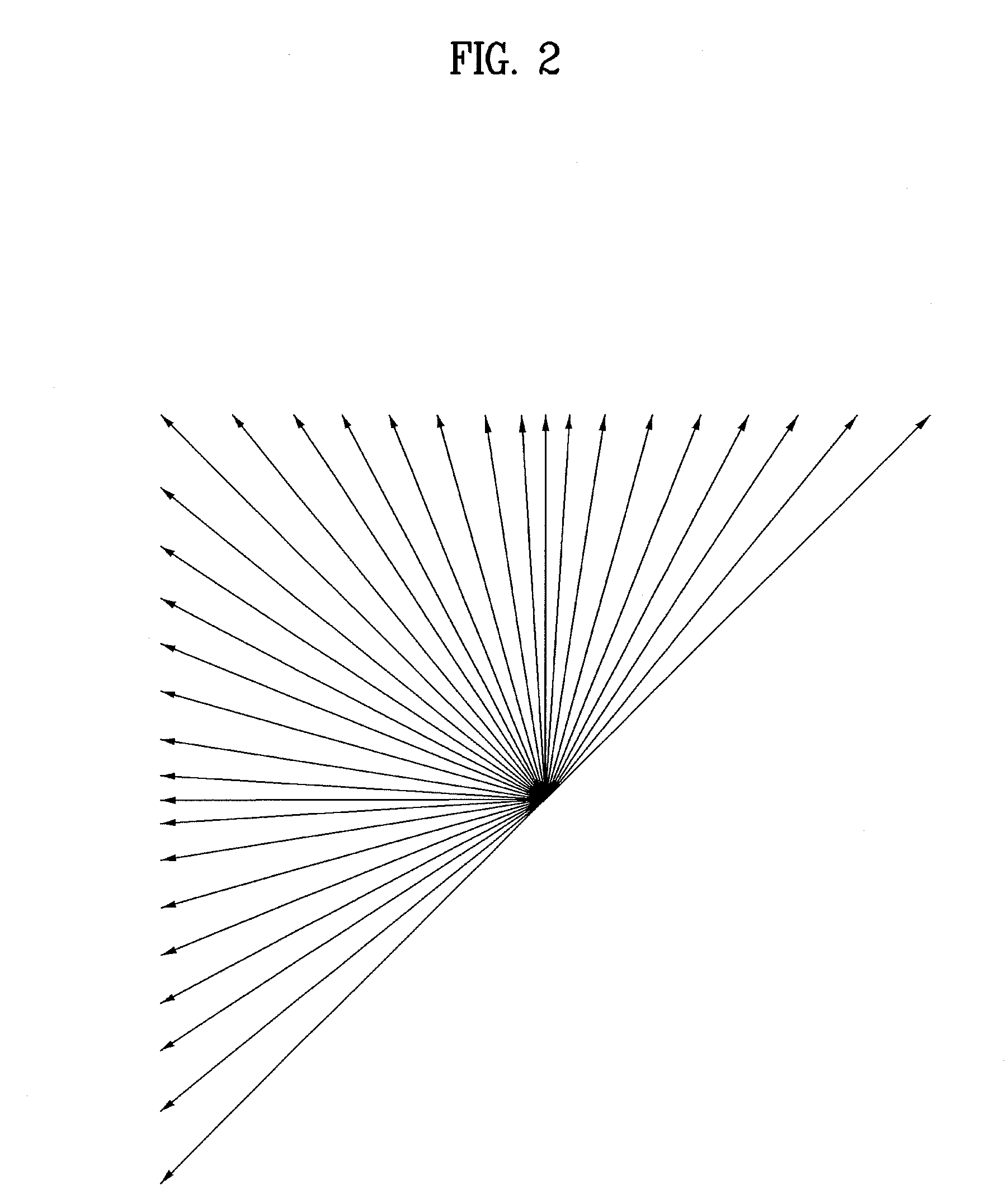
[0012]Accordingly, it is an object of the present invention to offer new intra prediction modes that provide more accurate predictions, when compared to previous intra prediction modes, of prediction units that are processed by a decoding unit.
[0013]Another object of the present invention is to provide a method for signaling the new intra prediction modes so that the decoding unit may properly identify the new intra prediction modes when predicting a current prediction unit.
[0014]Another object of the present invention is to minimize the maximum binary codeword length that is required to be transmitted along with digital video data for signaling each of the available intra prediction modes.

Problems solved by technology

This is an undesirable consequence of offering new intra prediction modes.
Therefore the real cost of increasing the number of total intra prediction modes available is in the number of total digital information that must be transmitted to identify all of the new intra prediction modes.
This in turn results in more and more information bits needing to be transmitted along with the actual video data bits, which obviously decreases the efficiency of the overall video signal compression.

Method used


Image

  • Intra prediction modes
  • Intra prediction modes
  • Intra prediction modes

Examples


first embodiment

[0094]According to the CIP prediction mode of the present invention, the first current prediction sample of the current prediction unit 1905 to be predicted will be the top left-most current prediction sample p1 as illustrated by FIG. 19. In this case, the local mean 1901 for predicting the first current prediction sample, p1, is comprised of three previously reconstructed samples from neighboring blocks 1902. This is the only instance where all three reference samples needed for the local mean 1901 will come from neighboring blocks. The intra angular prediction is also taken from a previously reconstructed reference sample, P, of a neighboring block. The CIP mode prediction for current prediction sample, p1, will then be the combination of a weighted value for the local mean 1901 combined with a weighted value for the intra angular prediction 1903 referenced from the reference sample P. The relationship can be seen by the following:

p1=[w1*(intra angular prediction)]+[(1−w1)*(local ...

second embodiment

[0097]According to the CIP mode prediction of the present invention, the scenario seen in step 0 in FIG. 20 begins with a current prediction unit 2001 that includes empty dots representing current prediction samples that need to be predicted and reconstructed. Adjacent to the current prediction unit 2001 are filled in black dots that represent samples from neighboring blocks that have previously been reconstructed. Then in step 1, four current prediction samples are first selected for prediction according to intra angular prediction modes referenced from neighboring block's previously reconstructed samples. These current prediction samples that are selected to be predicted are represented by the filled in gray dots. It is noted that although FIG. 20 illustrates one instance of four current prediction samples being selected to be predicted, it is within the scope of the present invention to select any four samples within the current prediction unit 2001. Also, although FIG. 20 illust...

third embodiment

[0102]Step 3 then illustrates the four selected samples from within the current prediction unit 2001 that were selected for CIP prediction in step 2, being fully reconstructed as represented by the filled in black dots in step 3. Now with all of the reconstructed samples from the neighboring blocks and within the current prediction unit 2001 itself available to be reference for CIP prediction, the remaining current prediction samples can be predicted according to the CIP mode. Therefore, as long as there are at least three reconstructed samples that are adjacent to a current prediction sample and at least one reconstructed sample from which to process an intra directional prediction on the current prediction sample, the current prediction sample can be processed according to this third embodiment of the CIP mode of the present invention.

[0103]It is also within the scope of the present invention to utilize more than just the reconstructed samples to the immediate left, top-left and t...


PUM


Abstract

New intra angular prediction modes and methods for decoding are offered for providing greater accuracy when processing predictions of digital video data blocks. One new method considers predicting a current prediction sample by taking the linear interpolation of two previously reconstructed reference samples that lay along a common angular line. Another new method offers a method for making previously unavailable samples from a neighboring block available as reference samples when predicting a current prediction sample. Another new method considers a new combined intra prediction mode that utilizes a local mean to predict a current prediction sample. And a new decoding method offers to rearrange the order in which video data blocks are predicted based on the intra prediction mode used for predicting the video data blocks.

Description

[0001]This application claims the benefit of U.S. Provisional Patent Application No. 61 / 345,583 filed on May 17, 2010; U.S. Provisional Patent Application No. 61 / 348,232 filed on May 25, 2010; U.S. Provisional Patent Application No. 61 / 348,243 filed on May 26, 2010; and U.S. Provisional Patent Application No. 61 / 349,197 filed on May 27, 2010, which are hereby incorporated by reference as if fully set forth herein.BACKGROUND[0002]1. Field of the Invention[0003]The present invention relates to a method and apparatus for performing intra prediction type decoding on digital video data that has been encoded using an intra prediction type prediction mode. The present invention also relates to a method and apparatus for providing the proper signaling to a decoding unit for informing the decoding unit as to the proper intra prediction mode to apply.[0004]2. Discussion of the Related Art[0005]Generally there are two methods for accomplishing video data compression in order to eliminate tempo...

Claims


Application Information

Patent Timeline
IPC IPC(8): H04N7/32H04N19/593
CPCH04N19/105H04N19/176H04N19/182H04N19/11H04N19/103H04N19/593
Inventor JEON, YONGJOONSUNG, JAEWONPARK, SEUNGWOOKPARK, JOONYOUNGJEON, BYEONGMOONLIM, JAEHYUNKIM, JUNGSUNCHOI, YOUNGHEE
Owner LG ELECTRONICS INC
Learn More