
High-impedance dc-isolating transmission line transformers

a transmission line transformer and high-impedance technology, applied in fixed transformers, one-port networks, waveguide devices, etc., can solve the problems of physical largeness, limited practicality of small-diameter coaxial cables, and limited impedance levels of about 100 ohms

Active Publication Date: 2011-11-17
AGILENT TECH INC
View PDF15 Cites 15 Cited by
  • Summary
  • Abstract
  • Description
  • Claims
  • Application Information

AI Technical Summary

Benefits of technology

[0016]In some implementations, the first port has a first port impedance, the second port has a second port impedance, the transmission lines have a characteristic line impedance, and the one or more pairs of transmission lines are interconnected at each port such that the first port impedance is equal to or greater than the characteristic line impedance and the second port impedance is equal to or greater than the characteristic line impedance.
[0017]In some implementations, the first port has a first port impedance, the second port has a second port impedance, the transmission lines have a characteristic line impedance, and the one or more pairs of transmission lines are interconnected at each port such that the first port impedance is equal to or less than the characteristic line impedance and the second port impedance is equal to or less than the characteristic line...

Problems solved by technology

Unfortunately practical small-diameter coaxial cable is limited to upper impedance levels of about 100 ohms, with 18 to 75 ohms being much more common.
Although high-impedance twin-lead can be readily constructed, it is physically large.

Method used


Image

  • High-impedance dc-isolating transmission line transformers
  • High-impedance dc-isolating transmission line transformers
  • High-impedance dc-isolating transmission line transformers

Examples


Embodiment Construction

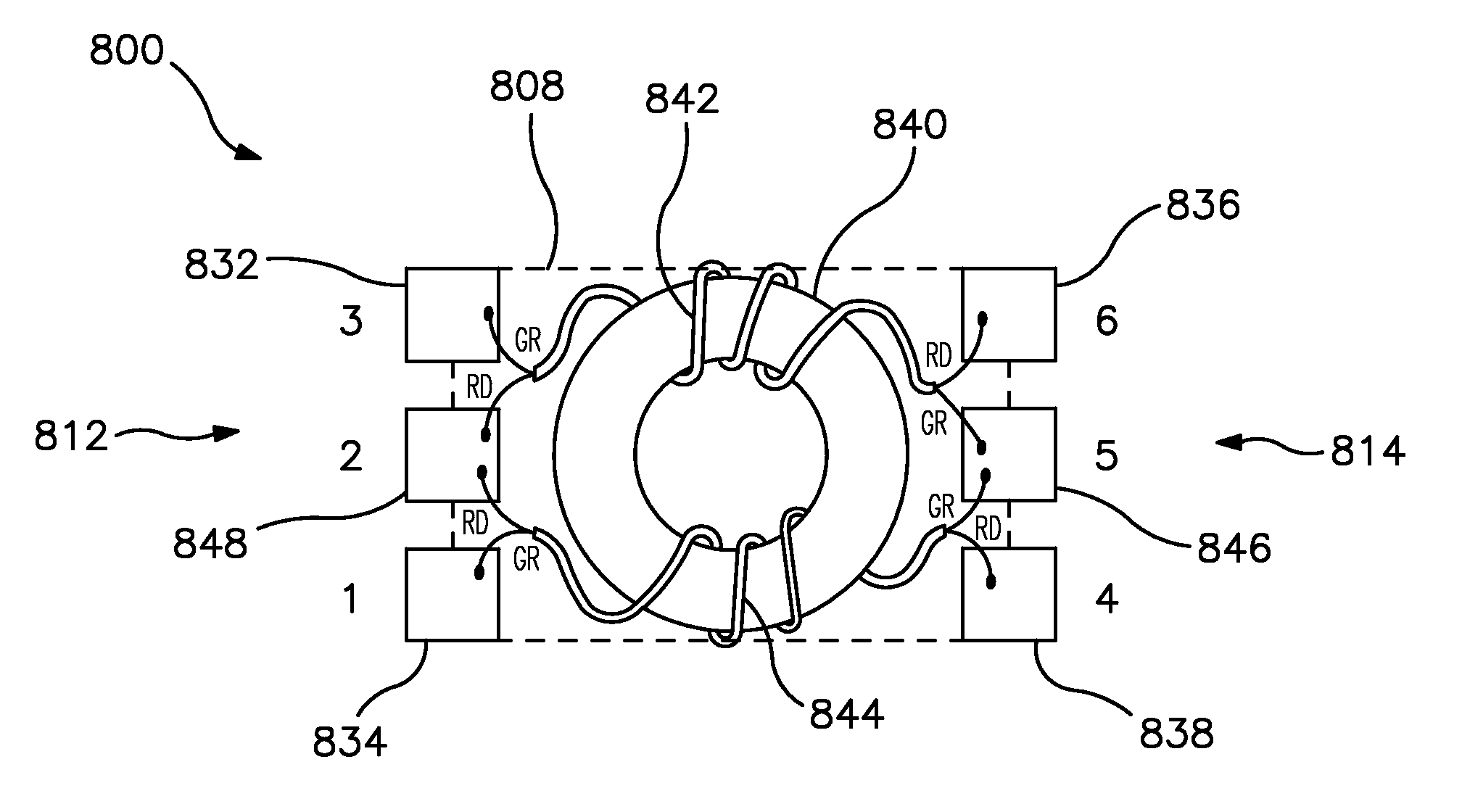
[0033]To address the problems discussed above, a new family of composite transmission line transformers (TLTs) is disclosed herein. These TLTs are “composite” transformers in the sense that they effectively include two or more transformers and may be constructed from two or more separate lengths of transmission line material. In general, these TLTs utilize combinations of series connections, parallel connections, and series-parallel connections at their input and output ports in such a manner that there is a significant relaxing in the requirement for the impedance of the transmission line material utilized to construct the TLT. This is particularly useful in the case of TLTs having at least one high-impedance port. Moreover, there is no DC connection between the input and output ports. In general, the composite transformers are constructed from an even number of separate transmission lines. At each port the transmission lines are first connected in series, in pairs, in such a manne...


PUM


Abstract

A composite transmission line transformer includes at least one core, a first port, a second port, and one or more pairs of transmission lines wound about the core(s). Each transmission line is in signal communication with the first port and the second port. For each pair, the transmission lines are interconnected in series at the first port and at the second port such that the first port and the second port are DC-isolated from each other.

Description

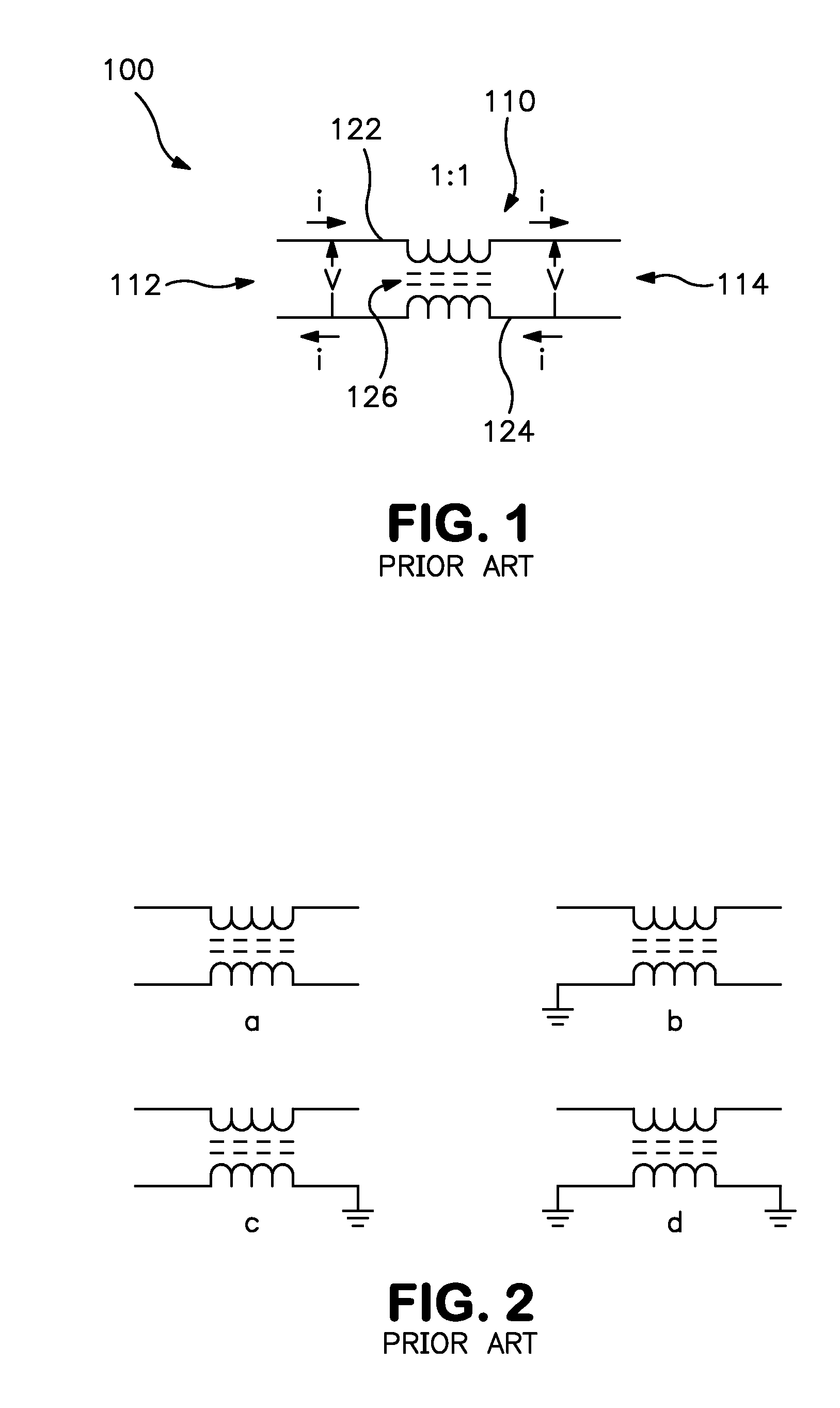
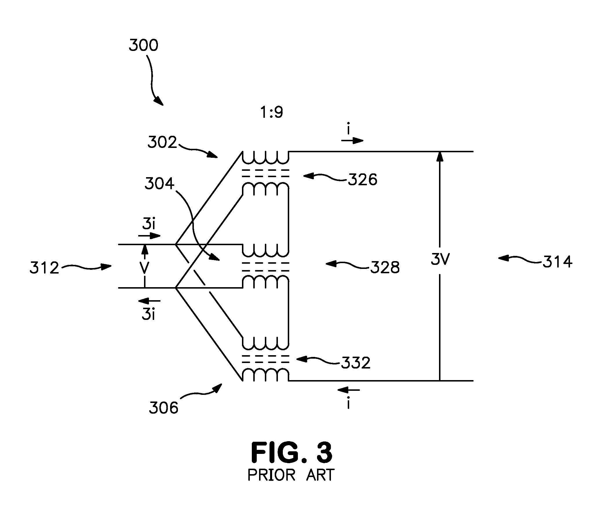
FIELD OF THE INVENTION[0001]The present invention relates generally to transmission line transformers. More particularly, the present invention relates to a family of transmission line transformers exhibiting high-impedance while utilizing relatively lower-impedance transmission lines, while exhibiting DC isolation between input and output ports and providing a center tap at each port.BACKGROUND OF THE INVENTION[0002]A transmission line transformer transmits electromagnetic energy by way of the traverse electromagnetic mode (TEM), or transmission line mode, instead of by way of the coupling of magnetic flux as in the case of a conventional transformer. The design and theory of various transmission line transformers are described in Sevick, J., “Transmission Line Transformers,”4th ed., Noble Publishing Corp., 2001.[0003]FIG. 1 is a schematic illustration of a Guanella-type 1:1 transmission line transformer (TLT) 100. The TLT 100 generally includes a single, two-conductor transmission...

Claims


Application Information

Patent Timeline
IPC IPC(8): H01F27/29
CPCH01F19/08H01F27/29H01F30/12H01F2019/085H01P5/04H01F5/04H01F27/2823H03H7/42
Inventor SCHOESSOW, MICHAEL J.
Owner AGILENT TECH INC
Learn More